This thread has been locked.

If you have a related question, please click the "Ask a related question" button in the top right corner. The newly created question will be automatically linked to this question.

ADS112C04: Problems with data read via I2C

Part Number: ADS112C04

Hi

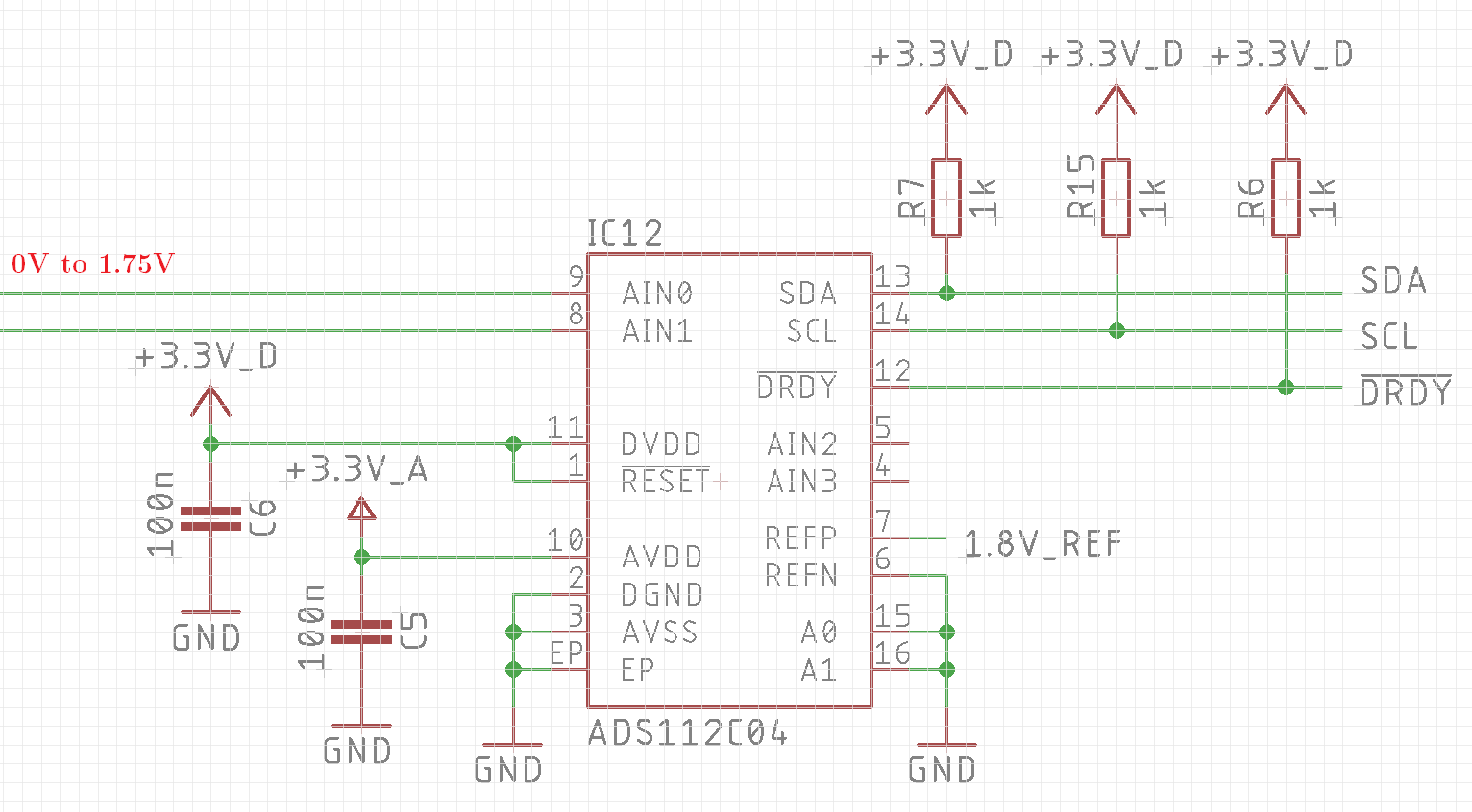
I use the ADS112C04 ADC with an external 1.8V reference  and a microcontroller to measure the output of an opa. Everything is fine if I write via I2C into some registers to configure the ADC (!DRDY pin is switching in continous mode, etc.). But if I read the converted data, they are crap (always approx. 0.5V on every channel, also on channels they are set to GND) and the ADC hold the SDA line an low level in the end (uC send a Stop condition, SCL line goes to high from the pullups, but SDA goes not to high).

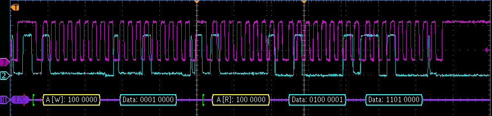
Picture shows my read process:

1. byte: slave adress (write mode)

2. byte: read data command

3. byte slave adress (read mode)

4. & 5. byte: data from the ADC (crap)

End: no stop condition, the ADC hold low level on SDA line

Have someone an idea what I do wrong?

Thanks

  • Hi Raphael,

    Welcome to the E2E forum!  It would be helpful to know the register settings you are using for the ADS112C04 as well as the input voltage and channels selected.  A schematic would also be helpful.

    The data being returned is 0x41D0 or 16848 decimal.  If you are using the external reference of 1.8V and a gain of 1, the value of a single code is +/- 1.8V/2^16 = 54.93uV.  The value being returned is the number of codes times the value of 1 code which for this example is 925.49mV.  As I have no idea what the actual input voltage is or how it is connected I cannot tell if this is close, but it is more than 500mV.  So I think you are making an error in your calculation.

    Also, you must make sure that the input voltage to the ADC is within the input range for the measurement.  If you are making a single-ended measurement (which is a measurement with respect to AGND) and if you are using a unipolar analog supply (AVSS is connected to AGND) then you must also disable and bypass the PGA.

    As to the SDA being held low at the end of the communication, this is a read operation by the micro which is holding SDA low and not the ADS112C04.  This would be most likely caused by the micro not sending a STOP command.

    Best regards,

    Bob B

  • Hi Bob, thanks for the fast response.

    My schematic:

    The I2C commands with them I work (register settings, slave adress and command bytes):

    //Register 0: Input = AIN1, Reference = GND, Gain = 1, PGA disabled and bypassed
    i2c_send2Byte(0b10000000, 0b01000000, 0b10010001);
            
    //Register 1: 1kS/s, Normal mode, Continuous conversion, External reference, Temperature sensor disabled
    i2c_send2Byte(0b10000000, 0b01000100, 0b11000010);
            
    //start continuous conversion
    i2c_send1Byte(0b10000000, 0b00001000);        

    //receive MSB & LSB and copy them into one uint16_t variable (0b10000001 = slave adress + read bit)
    uint16_t data = i2c_receive2Byte(0b10000001, 0b00010000);

    Input voltage on all analog channels is 0 to 1.75V (no negative voltages)

    Bob Benjamin said:

    The data being returned is 0x41D0 or 16848 decimal.  If you are using the external reference of 1.8V and a gain of 1, the value of a single code is +/- 1.8V/2^16 = 54.93uV.  The value being returned is the number of codes times the value of 1 code which for this example is 925.49mV.  As I have no idea what the actual input voltage is or how it is connected I cannot tell if this is close, but it is more than 500mV. 

    I am a little bit confused: 1.8V/2^16 = 27.46uV. With 16848 I returned 0.4627V. Why you have calculated 0.9254V? The Input wich I measure the 16848 value was on GND, so I expect a value near 0.

    Bob Benjamin said:

    As to the SDA being held low at the end of the communication, this is a read operation by the micro which is holding SDA low and not the ADS112C04.  This would be most likely caused by the micro not sending a STOP command.

    I send a stop command in the end, that's why I am also confused.

    Best regards

    Raphael

  • Hi Raphael,

    The LSB or value of a single code is +/-VREF/Gain/Full Scale Range (FSR). +/- is equivalent to 2 times the value.  So for the 1.8V reference, the LSB = 2 * 1.8V / 1 / 2^16 = 54.93uV.  See equation 8 in the ADS112C04 datasheet.

    For register 1 you describe using continuous conversion mode, but your register shows single-shot mode ( 0b11000010).  The correct setting would be  0b11001010 for continuous conversion mode.

    As far as the micro not correctly completing the STOP condition, I would verify that your function  i2c_receive2Byte() is working correctly.  The ADS112C04 will only ACK when receiving data and will not ACK when transmitting data.  This ACK will come from the micro.  As the micro is not effectively stopping as it should something is incorrect in the procedure.  Normally the micro would NACK the last byte received and then go to a STOP condition.  So as the micro sent an ACK, it would appear that the functionality within the receive function is anticipating another byte to be read instead of stopping.

    Best regards,

    Bob B