


Hi TI team,
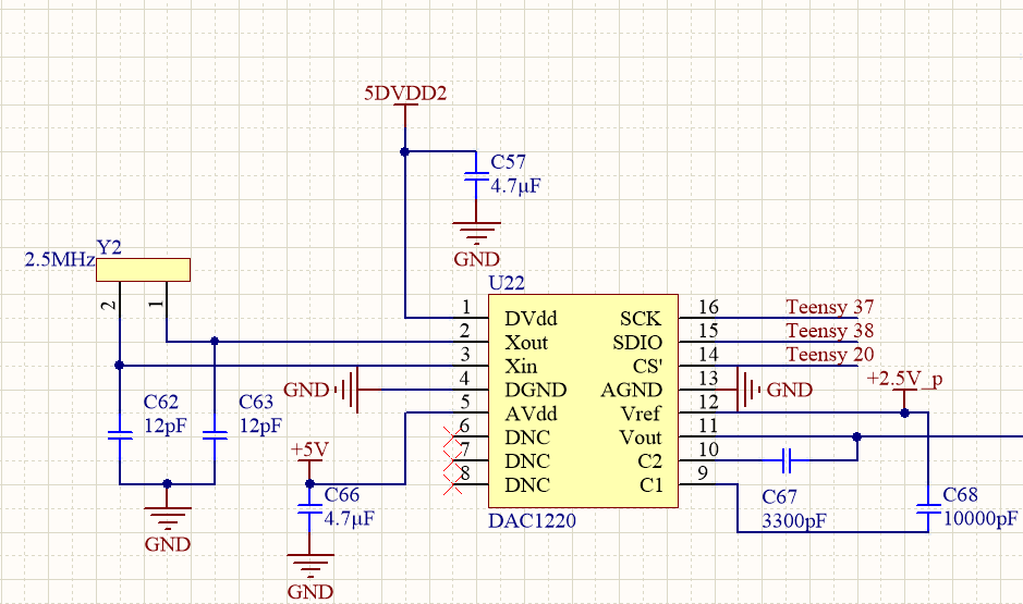
I am trying to interface DAC1220 from TI with Teensy 3.5 (Arduino compatible development board) Teensy supply rails are 3.3V, but pins are 5V tolerant. DAC1220 is powered with 5V (both AVDD and DVDD are 5V). My issue is I cannot get teens talk to DAC1220. Whatever I set in the code, the DAC1220 output stays at around reference voltage, 2.5V.
I checked the DAC1220 logic input level. DAC1220 requires min 2V input high voltage. Output high voltage of teensy (min) is around 2.7V - 2.8V. Teensy input high voltage requires at least 2.1-2.2V, this is also ok with DAC1220 specifications.
I tried my code with Arduino that has 5V supplies, It worked I was able to control the DAC and set the voltage I want.
My question is why the DAC is performs ok with 5V MCU, but not works with 3.3V MCU (logic levels meets the specs) ?
#define PIN_CS  20//enable
#define PIN_CLK  37//spi clock
#define PIN_DAT 38//spi data

uint32_t Millis = 0;
uint8_t  Buf[10];
uint8_t  Len = 0;
float cal = 1.00015;
float offset = 0.0004;
float voltageLimit = 4.99;
float v=3.58; // DAC out voltage
void setup() {
  Serial.begin(9600);
  pinMode(PIN_CS, OUTPUT);
  pinMode(PIN_CLK, OUTPUT);
  pinMode(PIN_DAT, OUTPUT);
  pinMode(13, OUTPUT);
  digitalWrite(PIN_CS, HIGH);
    digitalWrite(13, HIGH);

  reset();
}

void loop() {
  sendData(v);
delay(1000);
  }


void sendData (float setVoltage) {
  if (setVoltage < offset) {
    setVoltage = offset;
  }
  else if (setVoltage > voltageLimit) {
    setVoltage = voltageLimit;
  }
  uint32_t bitCode = voltageToBits(setVoltage * cal - offset);
  if (bitCode > 0xFFFFF) {
    bitCode = 0xFFFFF;
    Serial.println("input value clipped.");
  }
  Serial.print("Voltage: ");
  Serial.print(setVoltage, 4);
  Serial.print("  Bits: ");
  Serial.println(bitCode);
  Serial.println("-----------------------");
  Serial.println("");
  bitCode = bitCode << 4;

  digitalWrite(13, HIGH);
  digitalWrite(PIN_CS, LOW);
  shiftOut(PIN_DAT, PIN_CLK, MSBFIRST, 0x40);
  shiftOut(PIN_DAT, PIN_CLK, MSBFIRST, (bitCode & 0x00FF0000) >> 16);
  shiftOut(PIN_DAT, PIN_CLK, MSBFIRST, (bitCode & 0x0000FF00) >> 8);
  shiftOut(PIN_DAT, PIN_CLK, MSBFIRST, (bitCode & 0x000000FF));
  digitalWrite(PIN_CS, HIGH);
  digitalWrite(13, LOW);
}

uint32_t voltageToBits(float voltage) {
  return (voltage / 5.0) * pow(2, 20);
}

void reset () {
  digitalWrite(13, HIGH);
  digitalWrite(PIN_CS, LOW);
  //Reset DAC
  pinMode(PIN_CLK, OUTPUT);
  digitalWrite(PIN_CLK, LOW);
  delay(1);
  digitalWrite(PIN_CLK, HIGH);
  delayMicroseconds(240); //First high period (600 clocks)
  digitalWrite(PIN_CLK, LOW);
  delayMicroseconds(5);
  digitalWrite(PIN_CLK, HIGH);
  delayMicroseconds(480); //Second high period (1200 clocks)
  digitalWrite(PIN_CLK, LOW);
  delayMicroseconds(5);
  digitalWrite(PIN_CLK, HIGH);
  delayMicroseconds(960); //Second high period (2400 clocks)
  digitalWrite(PIN_CLK, LOW);
  delay(1);
  //Start Self-Calibration
  shiftOut(PIN_DAT, PIN_CLK, MSBFIRST, 0x05);
  //20-bit resolution
  shiftOut(PIN_DAT, PIN_CLK, MSBFIRST, 0xA1); //20-bit resolution
  digitalWrite(PIN_CS, HIGH);
  delay(600);
  digitalWrite(13, LOW);
  Serial.println("DAC reset sucessful");
  sendData(2.5);
}

void shiftOut(uint8_t dataPin, uint8_t clockPin, uint8_t bitOrder, int val, uint8_t bits = 8, uint8_t del = 10) {
  uint8_t i;
  for (i = 0; i < bits; i++)  {
    if (bitOrder == LSBFIRST)
      digitalWrite(dataPin, !!(val & (1 << i)));
    else
      digitalWrite(dataPin, !!(val & (1 << ((bits - 1 - i)))));
    digitalWrite(clockPin, HIGH);
    delayMicroseconds(del);
    digitalWrite(clockPin, LOW);
  }
}
Thank you for your help.


