This thread has been locked.

If you have a related question, please click the "Ask a related question" button in the top right corner. The newly created question will be automatically linked to this question.

ADS1015: ADS1015 and instrumentation amplifier

Part Number: ADS1015
Other Parts Discussed in Thread: INA826

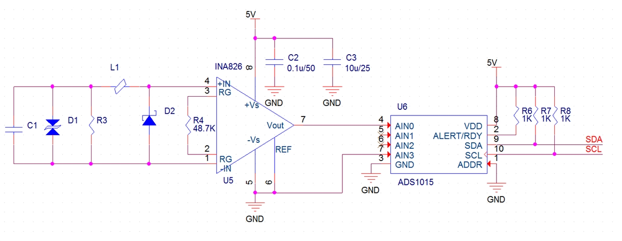
The output voltage of the instrumentation amplifier is 1-5V. With the differential input of ADS1015, is the solution of the schematic diagram correct?
By the way, see if the connection of the instrumentation amplifier is correct.
  • Hello,

    The basic connections to the ADS1015 look appropriate. Note that you're not showing a local decoupling capacitor for the ADC - recommend adding a 0.1uF.  Also, the I2C pull-ups could be increased to 4.7kΩ to save some power and increase the voltage swing on the driver outputs.

    The main thing missing in the schematic is a path for the INA826 input bias currents to return.  Please review 8.3.6 Input Bias Current Return Path in the datasheet for more information.  The short version is that you need to add a path for the input bias currents of the INA826 to return to GND.  This could be through your sensor if it provides a path from the inputs to GND, otherwise you'll need the external resistors shown in Figure 60.

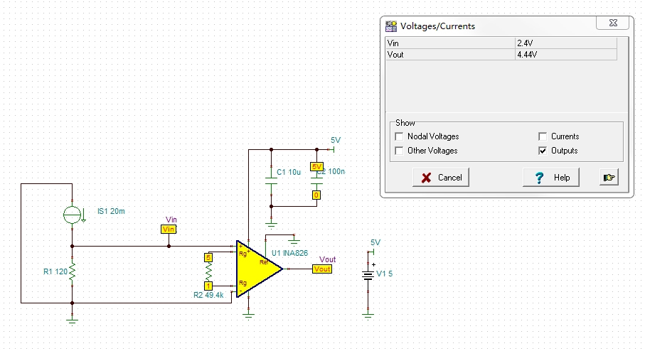
  • I added an input bias current loop, and the simulation result is incorrect. Please help point out design errors or others.

  • I added an input bias current loop, and the simulation result is incorrect. Please help point out design errors or others.

  • Hello,

    This looks to be an input common mode vs. output voltage limitation situation which is common with single-supply powered instrumentation amplifiers.  Figures 11 and 12 in the INA826 datasheet show the output voltage swing limits for different common-mode voltages for +5V/GND supply options. Note that with the common-mode basically at GND (0V) and the VREF also at 0V, the output swing is pretty limited. 

    You can use the calculator:  https://www.ti.com/tool/INA-CMV-CALC  to help determine the different achievable ranges and the SPICE model should mostly match.

    The solution will be to add a negative supply voltage to the INA826, or look for a different INA topology which allows for good output swing for common-mode voltages near the negative supply rails in single-supply operations.  I recommend you post a new thread to the amplifier team if you're interested in a different INA as they'll know the latest offerings better than me.