This thread has been locked.

If you have a related question, please click the "Ask a related question" button in the top right corner. The newly created question will be automatically linked to this question.

ADS131E08: DRDY won't be ready if DVDD is powered up before AVDD is powered up

Part Number: ADS131E08

Hi,

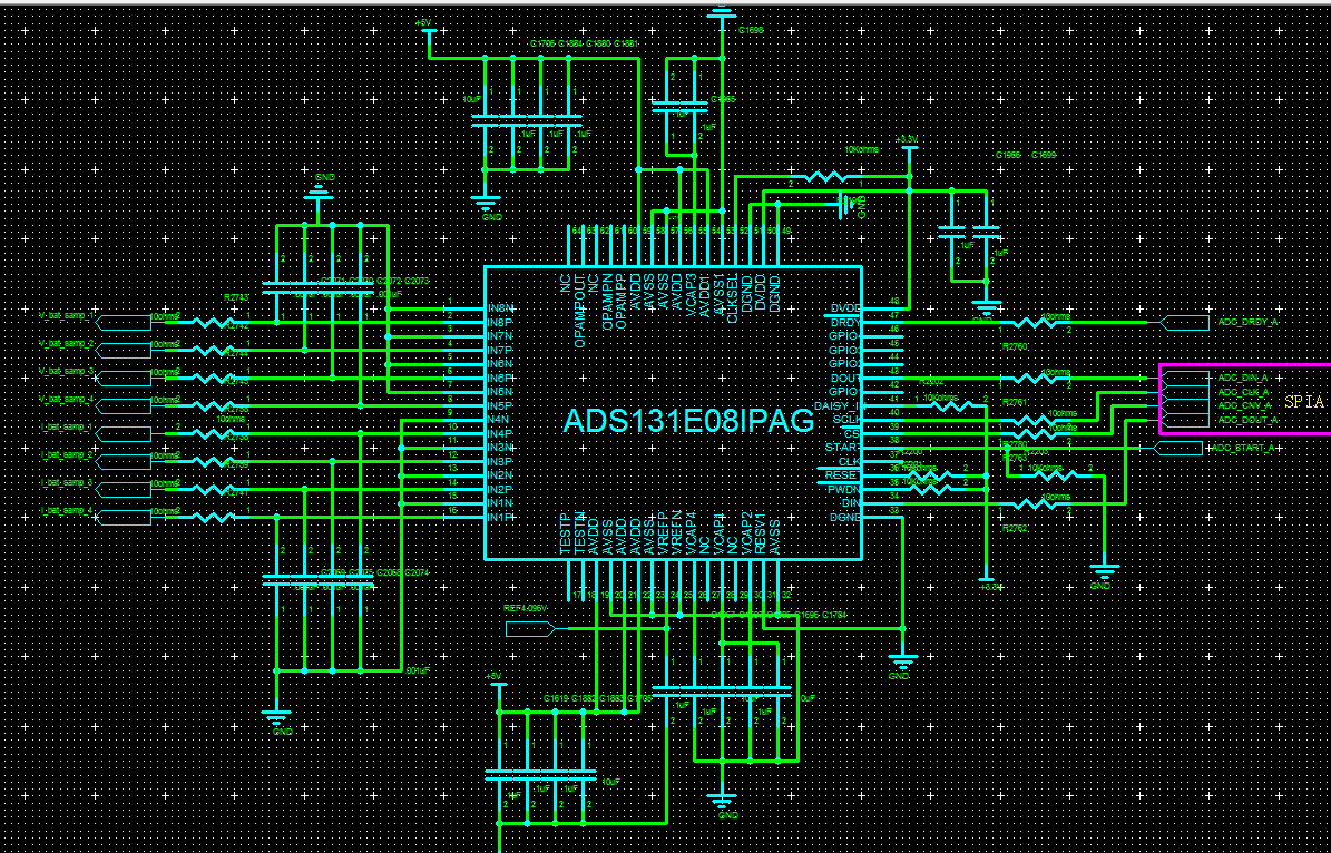
my customer's schematic is as below:

The tested by power up DVDD and AVDD seperately,

when AVDD is powered up prior to DVDD, the DRDY will send ready signal and the system could work well.

If DVDD is powered up prior to AVDD, the DRDY will never be ready, even after AVDD is stable.

Why would that happen? I don't see power sequence requirement in the datasheet.

  • Howard,


    I'm not certain about why the power-up order for AVDD and DVDD are not in the datasheet. However, there are some very specific recommendations about what needs to happen after the device powers up to set up the device properly. Perhaps these recommendations eliminate the AVDD/DVDD need to power one before the other.

    If you look at Figure 53 on page 50 of the datasheet, there's a diagram for the initial flow of operation for the device. I would read that carefully and make sure the customer follows the flow correctly. Of these commands, In particular, the /RESET pulse after tPOR may be needed for bringing up the digital core in the correct state.

    Looking at the schematic, does the customer have an available connection for /RESET? The use of /RESET is also described in the power-up timing in section 11.1 on page 61.

    To answer the original question, I would guess that if AVDD comes up before DVDD, and the device powers up cleanly, then the DVDD's power-on-reset worked properly. This holds the digital section in reset so that the digital section comes up in a good state. In the reverse, the AVDD coming up last may have caused some problem in the digital to cause it to be in a bad state.


    Joseph Wu

  • Joseph,

    In Figure 53, after we send the RESET signal, it's suggested to write 

    WREG CONFIG1 91h WREG CONFIG2 E0h //

    Set All Channels to Input Short

    WREG CHnSET 01h

    I'm not sure what's the purpose of this step.

    Can I just add the step "send the RESET signal" before the step "send the START signal" to reset the device to see if it can help eliminate the need of power sequence of AVDD and DVDD.

  • Howard,


    I'm sorry, I should have been a bit more clear. Figure 53 is used to show the initial flow and to test if the device is working properly. If you look at the paragraph before the figure, this is what it says:

    This section of the flow diagram is to make sure that the device is running in a known normal state. Shorting the inputs to mid-supply makes sure that inputs are set to a valid point within the input range. The readings would basically show a 0V input with low noise.

    If they are already able to determine that the device is correctly configured, they don't need to set the device this way.


    Joseph Wu

  • Joseph,

    It's caused by VCAP1 not risen up more than 1.1V, we've delayed the reset and the problem solved.

  • Howard,

    Thanks for letting me know! If there are any other questions, feel free to post back.

    Joseph Wu