Part Number: ADS1299
Hello everyone
We recently made a custom board of ADS1299 with bipolar supply. We set AVDD = +2.5V, AVSS = -2.5V and DVDD = 3.3V.a
During testing we set all channels to Supply Measurement mode(CHnSET[2:0] = 011). As per datasheet channel no 1,2,5,6,7 and 8 should provide [0.5 × (AVDD + AVSS)] and channel no 3 and 4 should provide DVDD/4 (See page 21 of Datasheet).
Channel 3 and 4 are giving output as 0.825V ((DVDD = 3.3) / 4). So this part is correct. However all other channels are providing 2.5V instead of 0V as expected because ((+2.5 - 2.5)/2). This fact was further demonstrated in ads demonstration kit document (page 23).
We provided both polarity signals like +-0.1mV and +-0.5mV DC signals from precision DC source. ADS1299 is reading those values correctly when in Normal Electrode mode. Temperature reading and Internally generated square wave is being read correctly also. Since both polarity signals are being read correctly, we assume we are providing correct power supply.
I may be missing some simple point but any help will be highly appreciated.
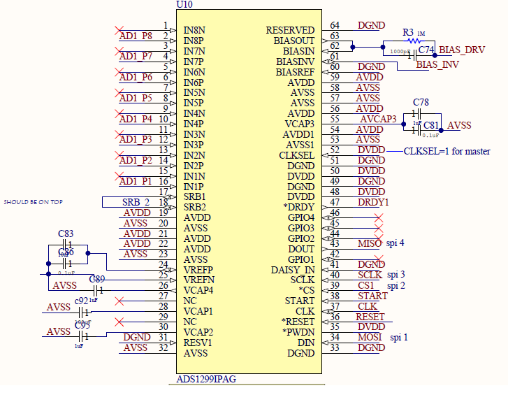
Schematic of ADS1299 part of our board is below