This thread has been locked.

If you have a related question, please click the "Ask a related question" button in the top right corner. The newly created question will be automatically linked to this question.

ADS8698: ADC read issue

Part Number: ADS8698
Other Parts Discussed in Thread: ADS8688

Hi,

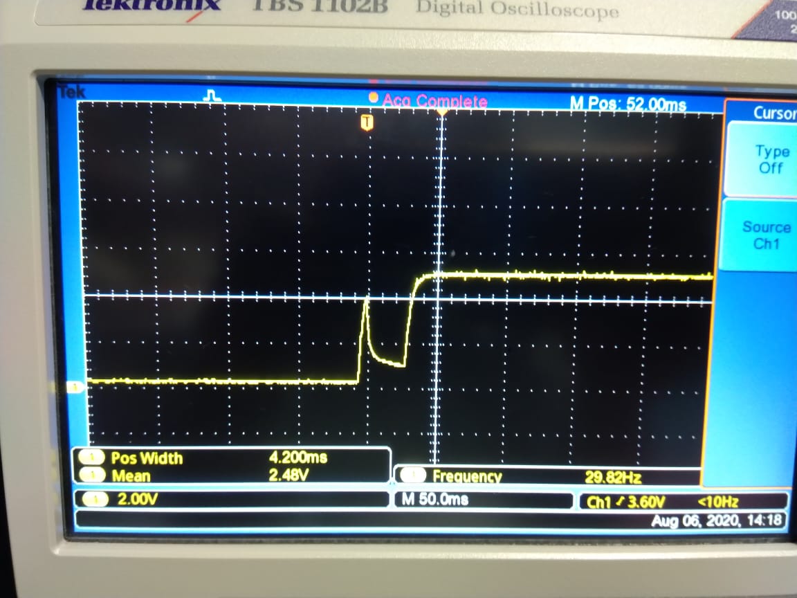
I am using ADS8698 ADC. When I am switching ON the power supply, I am facing the voltage drop initially in +5V, +3.3V and also Reset (as shown in figure 1). Due to this, all the channels in ADC read some garbage value (as shown in figure 2). Is there anything I can do in software configuration to solve this issue.

Please help me


  • Hi mahesh,

    Please clarify:

    1. Are these +5V and 3Vpower supplies (AVDD,DVDD)? Can you show me power the supplies signal captured with a scope when powered on? The Rest is an input to the ADC, it sounds like your external power supplies and the controller created the "drop" issue.

    2. It's hard to see your code also I do not know your input signal. Did you get these code exactly during the "drop" pulse?

    I think you may have to solve the "drop" issue caused by the power supplies or the controller firstly.

    Thanks&regards,

    Dale 

  • Hi Dale,

    Thanks for your reply,

    1.  The figure 1 shown previously is of +5V AVDD. and the waveform is same to +3.3V DVDD also.

         Due to this power drop, the reset generated from ADC is also getting dropped as the controller gets ON  and OFF.

    2.  The input voltage connected to ADC is 0V to all channels, but the ADC starts reading 4.9V as shown in Figure 2.

    When I solve the voltage drop issue, the ADC reads fine. But I need to sort this issue with software since my design is in production stage.

    I am wondering if the ADC get stuck in some mode during power drop, can I bring to normal mode using internal registers or reset ?

    Please help me to sort this issue through software as I am helpless now.

    Regards,

    Kumar

  • Hi Kumar,

    Firstly, to be clear, this is NOT an issue, the large output code you got is a correct response from the ADC because the voltage reference definitely has a same drop caused by the voltage drop on the power supplies whatever you are using an external voltage reference or the internal reference on the ADS8688. The conversion code is got from the analog input signal compared with the reference voltage. Under normal operation, when the ADC's input is 0V, the output conversion code is around 0x20000 for ADS8698 which is not all 0, see the transfer function for ADS8698 below. Hence, the conversion code will be increased when there is a drop on the reference and the reference voltage becomes smaller, this is the reason why you saw a higher voltage converted from the conversion code.

    Secondly, since this is only happening when the power supplies are switched on, will the conversion code be normal after the power supplies become stable? If so,  can the following solutions accepted in your system?

    1. Add a delay in the software and wait to start the conversion after the power supplies are stable? the required waiting time is short from your captured waveform.
    2. Get rid of these incorrect data when the power supply drop is ongoing and only use the data after the power supplies are stable.

    Thanks.

    Regards,

    Dale

  • Dear Dale,

    My main issue is that the conversion codes are not getting normal even when power supplies are stable after the voltage drop.

    I already tried keeping a delay of 5 seconds to read ADC after the supplies have become stable, but no luck.

    My ADC range is set to 0 to +5V. As you can see, the voltage +4.9 is read on all the channels even after the power supplies have got stable (was read after 10 seconds).

    Sometimes it also shows as +2.5V.

    Thanks,

    Regards,

    Kumar

  • Hi Kaumar,

    Did you try to reset the device through /RST pin 2? the reset command in software can only reset the program registers, so have to use the hardware reset.

    Also, when you said "The input voltage connected to ADC is 0V to all channels", did you short all inputs to the ground or just leave them floating?

    Regards,

    Dale

  • Hi Dale,

    I did try doing reset the device through reset pin 2, multiple times but the problem remains same.

    All the inputs are connected to ground using pull down resistor.

    Regards,

    Kumar

  • Hi Kumar,

    Thanks for your information. Unfortunately, if a hardware RESET can not reset the device back to the normal condition, the only way to recover the device is to cycle the power supply especially AVDD.

    Another possible approach you could try is using a large value capacitor on the power supply pin to make the drop smooth and slow, however this can not guarantee to solve the issue, the root reason to have issue was  voltage drop generated by the power supply circuit in your system. Use a 5V TVS diode to avoid overshooting on the power supply pin of the ADC when you try this approach.

    Best regards,

    Dale

  • Hi Dale,

    Thanks for your response.

    On power ON, I kept reset Low until I get stable supply and then held high. Now my ADC is working fine.

    Thank you for your immense support.

    Regards,

    Kumar

  • Hi Kumar,

    Thank you for update.

    Best regards,

    Dale