This thread has been locked.

If you have a related question, please click the "Ask a related question" button in the top right corner. The newly created question will be automatically linked to this question.

ADS124S08: Single-ended input, PGA enabled, Single 5V supply for AVDD

Part Number: ADS124S08

My application needs 12: 0-5V ADCs, but would also like to be able to use the PGA for smaller single ended signals. 

I think I understand how to connect and program the part, but just want to confirm.  Is this right?

Using the model below:

  1. Put a 1uF cap on REFOUT to REFCOM
  2. Tie REFCOM to AVSS
  3. Tie REFOUT to AINCOM to act as AINn
  4. AVDD to +5V
  5. REFP0 to +5V
  6. REFN0 is not connected
  7. Program REFSEL=0
  8. Program REFCON=1
  9. Program MUXN to AINCOM
  10. Program MUXP to the desired Channel to be AINp
  11. Repeat previous for next channel. 

  • Hi Mike,

    It looks like maybe you were trying to attach a picture.  You need to use the appropriate icon for uploading files and graphical images to the post.

    It is not clear your total intent.  You have enabled the internal reference for a bias point, but you are using the analog supply as the reference.  To use the REF0 inputs REFN0 must go to AVSS.  Are you using the low-side switch for this?  If so, the AVSS-SW pin must be connected to AVSS (AGND) and you must make sure that low-side switch is closed with the proper PSW setting in the IDACMAG register (0x06).

    The other point that is not clear is you are setting a 2.5V bias point midway between the supplies at AINCOM as a pseudo differential measurement.  With a 5V reference this will limit the input measurement range to 1/2 of the full-scale range. +/-2.5V as opposed to +/-5V.  With a 5V reference you can directly measure the input voltage from 0 to 5V. If you want to maximize the dynamic range, then you would use the internal reference as the reference source as well as using the 2.5V at AINCOM.

    Now for this kind of single-ended measurement while using a unipolar analog supply, you are limited to a gain of 1 and the PGA must be bypassed.  This is the default setting in the PGA register (0x03).  If the PGA is enabled, then the input range excludes measurements close to AVSS or AVDD as those inputs would be outside of the linear range of the PGA.

    Best regards,

    Bob B


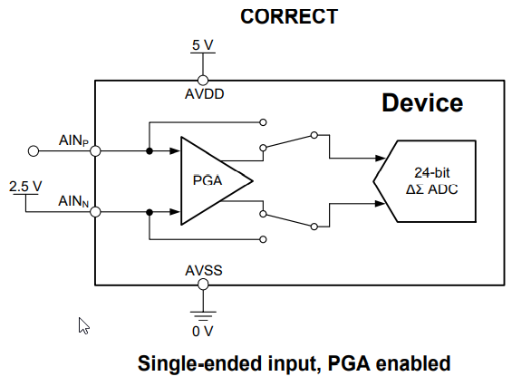
  • Sorry, I noticed but could not edit the post. I've attached it again, but it still does not look right. It's just a PNG of the diagram from Figure 117, Page 97 of the datasheet for "Single-ended input, PGA enabled"

    That second diagram in the left column shows: Unipolar 0-5V supply, 2.5V on AINn, and an input on AINp, with PGA enabled. 

    Yes, I have AVSS-SW to AGND. Noted  IDACMAG  must be set. 

    I understood that for 0-5V I don't need a PGA, But what if I also wanted to measure smaller signals using a gain of 8? 

    Are you saying that 2.5V on AINn configuration is for measuring +/-2.5V with gain of 1 or  2.5V +/- some smaller value with gain? 

  • Hi Mike,

    From the posted image, this measurement is normally set to a gain of 1, but the measurement range is limited to the input range as specified in the datasheet in section 7.3.  In this configuration the reference would be 2.5V, and AINP would be limited to:

    So if you apply gain and your signal is sufficiently far from AVDD or AVSS then you would be able to make the measurement.  However, if the measurement is from 0 to 500mV relative to AGND, and you apply gain you will be operating outside of the linear range of the PGA and the measurement will contain error.  It is not that the input would necessarily be beyond the full-scale range but rather that the input is in violation of the absolute input voltage relative to AVSS (AGND).

    Best regards,

    Bob B

  • Bob, thanks for that explanation. What I'm understanding then is that the PGA is really only useful when making differential measurements because of non-linearity rail to rail.. So the 2.5V ref is just used to bias the PGA, and the A2D is still referenced to AVDD and AVSS. 

    So to use the PGA, AINCOM must be connected to REFP0 with 2.5V, and routed to AINn  correct?

    This seems mutually exclusive with measuring 0-5V with no PGA, since AINCOM must be connected to AVSS right? 

  • Hi Mike,

    I think you are getting things mixed up.  The ADS124S08 can use a variety of references and reference input voltages.  One method is to use the analog supply.  Another method is to use the internal reference which is 2.5V.  The internal reference has this limitation because AVDD can go as low as 2.7V and we want to be able to provide a good, clean and stable reference for the ADC.

    It is the reference that determines the full-scale range at a gain of 1.  The ADS124S08 takes a difference measurement and the result is binary two's complement.  If AINP is greater than AINN relative to AVSS, then the result will be positive.  If ANN is greater than AINP relative to AVSS the result is negative. So at a gain of 1, the full-scale range is +/- VREF.

    If you want to make a single-ended measurement where the measurement is relative to AGND, and if that measurement ranges from 0 to 5V, then you can choose which full-scale range you would like to use as well as whether or not you want to enable the PGA or disable the PGA at a gain of 1.

    If you set the reference to the analog supply, and if the analog supply is 5V, then the full-scale range is +/- 5V.  If you tie AGND to one of the analog inputs and set that input to AINN, then the sensor output can be connected to one of the other analog inputs and set to AINP in the mux selection register.  In this case, AINP will always be greater than AINN so you will only see positive output codes.  Also, because the AINN is connected to AGND, this violates the input range of the PGA so for this measurement case you need to disable and bypass the PGA.  The advantage here is you can read the result directly and apply the code returned to directly convert to a positive voltage value.

    If you use the 2.5V internal reference, the full-scale range now becomes +/- 2.5V.  The total range is 5V, but you must offset the measurement to be able to read a total of 5V.  If you set AINP to the 2.5V reference output of the ADC, and if you set your sensor output to AINN you now would subtract 2.5V from each measurement. (You could also make AINN 2.5V and add 2.5V instead just remember that the output code is AINP relative to AINN).  In this way the total output codes becomes +/- 2^23, and to get the 5V range you need to factor the offset of 2.5V.

    The tricky consideration is the absolute input voltage relative to AVSS as this will determine whether or not you can enable the PGA.  If the sensor output has limitations where the sensor cannot drive all the way to the supply rails, then often you can enable and use the PGA.  However, if the sensor can traverse the full range of the analog supply, then you will need to disable the PGA and bypass.  The AINx input connected to the reference is not a problem, but the sensor output signal will be an issue if you are at or very close to the supply rails.

    One more thing, AINCOM is the same as any other analog input.  We could have labeled it differently, but AINCOM just helps in setting up the inputs for single-ended (or biased input) measurements.

    Best regards,

    Bob B