This thread has been locked.
If you have a related question, please click the "Ask a related question" button in the top right corner. The newly created question will be automatically linked to this question.
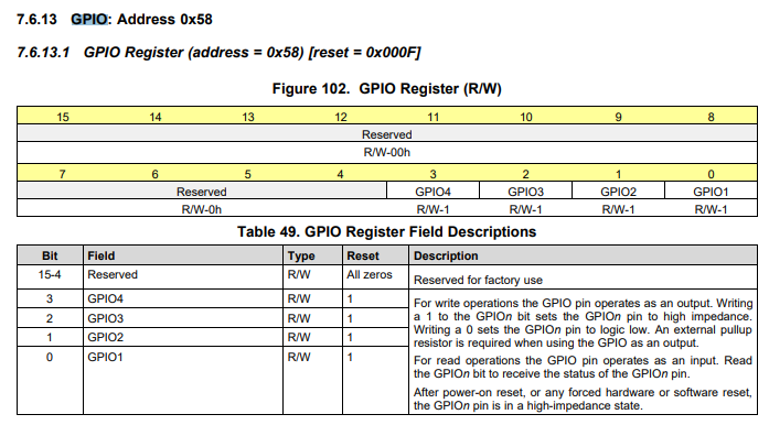
I have read the AMC7834 data sheet and the AMC7834EVM user guide and I see how to set the register to set up GPIO1 - GPIO4 as inputs or outputs. What I do not find is how to set up the functionality of these I/O. How are they utilized?
Hi Tom,
The GPIO is controlled with a single register. The outputs are open-drain, mean they can be held low, or are high impedance. If you want to use the pin as an output, you write the GPIO register to either 0 or 1. When 0, the pin held to ground. When 1, it is high-z. It requires an external pull up resistor to actually go to logic 1.
If you want to use the pin as an input, you just write 1 to the register and omit the pull-up resistor. When read, the register will reflect the current polarity of the pin.
Thanks,
Paul