This thread has been locked.

If you have a related question, please click the "Ask a related question" button in the top right corner. The newly created question will be automatically linked to this question.

ADS1115: Differential Mode, estrange readings when using the 4 channels simultaneously.

Part Number: ADS1115
Other Parts Discussed in Thread: ADS1015,

Hi every one!!

I am new in the forum, hope can help me¡¡

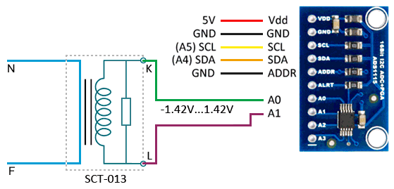
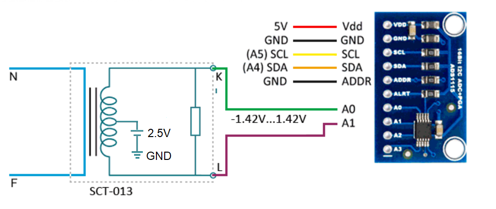
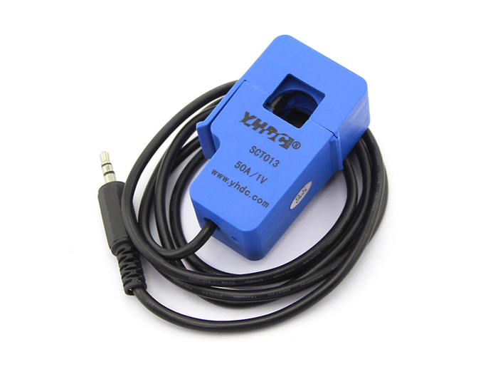
I am working with Arduino DUE, two   SCT-013 50A/1V and the ADS1115 in differential mode, i connect the first SCT-013 on A0/A1 channels and  the second one on A2/A3 channels, i am using the Adafruit_ADS1015 library,  when  i am measuring one charge on any of the two differential ports don't have any problem, the readings are OK, but when i have two charges simultaneously, I get  estrange readings in both differential ports, its seems to be a interference or noise input between the channels.

How can i fix the problem?.

Thanks in advanced.

Greetings.

  • Manuel,


    First, what are you measuring and how do you have each channel configured? When you are making measurements for each channel, what values do you get when you are making the measurements separately? and what values do you get when you connect all measurements to the same system? It helps to know what values you get can compare them what values you expect. Also, it might help to show a schematic of your system.

    There could be a few different things that could be a problem. First, the ADC can only measure voltages that are within the input range of the ADC. For this device, the input can only be from GND to VDD. If any input pin voltage is beyond these voltages, the input multiplexer may not be able to switch the channels in and out. For the measurement voltages and the ADC, they should have some sort of common ground. 

    Another issue is the method of reading data. If the device is in continuous conversion mode, then the device is repeatedly converting. If there is a change in the configuration register, the change does not take place until after the conversion in progress completes. This might lead to a confusion about what data you get and when because if you read the data to early, you may get the data from the previous channel.

    In most cases, I recommend that you use single-shot conversion mode. Start the conversion with the new configuration. Wait the nominal data period, at 10% for internal clock variation and then add 20us for the device to start up (for the device at 128SPS, this would be about 861us). Then read the data. Repeat for each channel or configuration you want.

    Anyway, look through the questions as the start of my post and we can discuss it when you return with answers.

    Joseph Wu

  • Joseph

    Thank for you quick response, I will try to understand how to implement single-shot conversion mode through Adafruit library, this is the code that i´m using to read the the values from SCT-013 50A/1V:

    #include <Adafruit_ADS1015.h>

    #define ads_add_0 (0x48)

    Adafruit_ADS1115 ads0(ads_add_0);

    void setup() {

    ads0.setGain(GAIN_TWO); // ±2.048V 1 bit = 0.0625mV
    ads0.begin();

    }

    float getCorriente(byte bomba)
    {
    long tiempo = 0;
    long rawAdc = 0;
    long minRaw = 0;
    long maxRaw = 0;
    float voltagePeak = 0;
    float voltageRMS = 0;
    float currentRMS = 0;


    switch (bomba) {
    case 1:
    if (BomEnc1 == 1) {
    tiempo = millis();
    rawAdc = ads0.readADC_Differential_0_1();
    minRaw = rawAdc;
    maxRaw = rawAdc;
    while (millis() - tiempo < 2000)
    {
    rawAdc = ads0.readADC_Differential_0_1();
    maxRaw = maxRaw > rawAdc ? maxRaw : rawAdc;
    minRaw = minRaw < rawAdc ? minRaw : rawAdc;
    }
    maxRaw = maxRaw > -minRaw ? maxRaw : -minRaw;
    voltagePeak = (maxRaw * (FampB1)) / 1000;
    voltageRMS = voltagePeak * 0.70710678118;
    currentRMS = voltageRMS * 50;
    currentRMS = currentRMS / 10000;
    Serial.print("medida currentRMS B1:");
    Serial.println(currentRMS);
    return (currentRMS);
    }
    else return (0.00);
    break;

    case 2:
    if (BomEnc2 == 1) {
    tiempo = millis();
    rawAdc = ads0.readADC_Differential_2_3();
    minRaw = rawAdc;
    maxRaw = rawAdc;
    while (millis() - tiempo < 2000)
    {
    rawAdc = ads0.readADC_Differential_2_3();
    maxRaw = maxRaw > rawAdc ? maxRaw : rawAdc;
    minRaw = minRaw < rawAdc ? minRaw : rawAdc;
    }
    maxRaw = maxRaw > -minRaw ? maxRaw : -minRaw;
    voltagePeak = (maxRaw * (FampB2)) / 1000;
    voltageRMS = voltagePeak * 0.70710678118;
    currentRMS = voltageRMS * 50;
    currentRMS = currentRMS / 10000;
    Serial.print("medida currentRMS B2:");
    Serial.println(currentRMS);
    return (currentRMS);
    }
    else return (0.00);
    break;

    }
    }

    I will try to implement single-shot conversion mode, and see if this fix the problem, i will reach you when do it.

    Thanks very much for your help¡

    Manuel

  • Joseph

    This is the schematic, the first SCT013 is connected to A0 - A1, the second one on A2 - A3 :

    SEN-SCT013 SENSOR DE CORRIENTE NO INVASIVO MAXIMO 100Amp SALIDA ...Sensor de corriente eléctrica no invasivo con Arduino y SCT-013

  • Manuel,


    One of the images in your last post didn't make it through. In your next response, why don't you add it then. In the mean time, I think I have a basic understanding of your system measurement.

    I think the problem is that the your measurement does not have a defined common-mode input. As I mentioned in my last post, the absolute value of the inputs (AINP and AINN) must be within the GND to VDD range to be accurately measured by the ADC. Howeveer, in your setup, the output of the transformer does not have a common voltage to ensure that the inputs are within this range. They could float outside GND to VDD and not be accurately measured.

    To ensure that the inputs are within the range of the ADC you would need a setup similar to this:

    Here, the midpoint of the transformer output would be tied to 2.5V, which is the midpoint of the ADC supply (and midpoint of the ADC input range). The GND connection would be the same as the ADC ground. This would ensure that the input is in the input range for measurement.

    For your setup, it may not be easily done if your output doesn't have center tap for this kind of setup. If you can restrict your outputs to only positive outputs, then you can tie the negative input to ground. This would at least be a good test of the inputs.

    If you can't restrict your inputs to only positive inputs, you may need some sort of FDA for ensuring the input range.


    Joseph Wu

  • Joseph

    here the images missed:

    Sensor De Corriente Alterna 50A Transformador - SCT-013-050 ...

    The device doesn't have center tap, how can I restrict the inputs to only positive ?

    Thanks for you help¡

    Greetings

    Manuel


  • Sorry can't upload the last image, don´t know why.....

  • Manuel,

    When you insert images into the post, you can't use copy/paste (ctrl-c/ctrl-v). You need to use the picture icon (that says Insert /Edit Media).

    Joseph Wu

  • Manuel,

    I haven't heard from you for a while. Were you able to solve your measurement problem. In my previous posts, I'd mentioned that i thought that the problem was making sure that your sensor input is within the common-mode input range of the ADC.

    I'll close this thread for now, but if you're continuing to have problems. post back and we can continue to work on this issue.

    Joseph Wu