This thread has been locked.

If you have a related question, please click the "Ask a related question" button in the top right corner. The newly created question will be automatically linked to this question.

ADS1248: SPI timing

Part Number: ADS1248

Hi Team,

I am having a hard time with SPI communication. From datasheet of ADS1248 what I understood is that as long as I send clocks in multiple of eight I can send data back to back. But what I am experiencing is that I need to wait for approximately 20 micro seconds between each transfer. Any delay less than 20 microseconds resulting in communication failure. Is this delay is required? I haven't seen anything like that in datasheet. 

        SpiaRegs.SPITXBUF                   = 0x1640; // Send the SDATAC command and WREG Command 1st byte
        DELAY_US(20);
        SpiaRegs.SPITXBUF                   = 0x030A; // WREG Command 2nd byte and MUX0 register value
        DELAY_US(20);
        SpiaRegs.SPITXBUF                   = 0x0020; // VBIAS register value and MUX1 register value
        DELAY_US(20);
        SpiaRegs.SPITXBUF                   = 0x404A; // SYS0 register and WREG 1st command byte
        DELAY_US(20);
        SpiaRegs.SPITXBUF                   = 0x0105; // WREG 2nd command byte and IDAC0 register value
        DELAY_US(20);
        SpiaRegs.SPITXBUF                   = 0x03FF; // IDAC1 register value and NOP command
        DELAY_US(20);
        SpiaRegs.SPITXBUF                   = 0xFF04; // NOP command and ADC SYNC
        DELAY_US(2);
        GpioDataRegs.GPASET.bit.GPIO14      = 1; // Clear CS/ pin to HIGH
        DELAY_US(201000);

        // Reading conversion result of input channel 1

        GpioDataRegs.GPACLEAR.bit.GPIO14    = 1; // Clear CS/ pin to LOW
        r1                                  = 0x00000000;
        r2                                  = 0x0000;
        r3                                  = 0x0000000;
        SpiaRegs.SPITXBUF                   = 0xFF12; // NOP and RDATA
        DELAY_US(20);
        SpiaRegs.SPITXBUF                   = 0x4000; // WREG Command 1st byte and 2nd byte
        DELAY_US(20);
        r1                                  = SpiaRegs.SPIRXBUF; // first 16 bits of conversion result MSB first
        SpiaRegs.SPITXBUF                   = 0x254B; // MUX0 register value and WREG Command 1st byte
        DELAY_US(20);
        r2                                  = SpiaRegs.SPIRXBUF; // Second 8 bits of conversion result and remaining 8 bits of junk value
        r3                                  += (r1 << 8) + (r2 >> 8);
        DELAY_US(20);
        SpiaRegs.SPITXBUF                   = 0x00AB; // WREG Command 2nd byte IDAC0 register value
        DELAY_US(20);
        SpiaRegs.SPITXBUF                   = 0xFF04; // NOP and SYNC command
        DELAY_US(2);
        GpioDataRegs.GPASET.bit.GPIO14      = 1; // Clear CS/ pin to HIGH

The other thing is that for this 20 microsecond delay I am only observing roughly 4.48 microseconds in CRO. Why this happens? But the SPI clock frequency 1 MHz is correctly observed. 

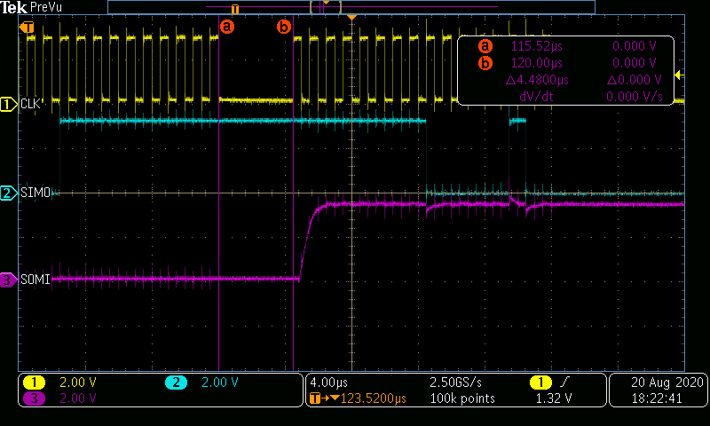
Crystal frequency is 100 MHz and SPI clock frequency is 1 MHz which correct.

Thank you,

Vineeth N

  • Hi Vineeth,

    One thing to consider is tSCCS Delay time, CS rising edge after final SCLK falling edge. It may be that this is sometimes being violated.

    Another possibility is the noise seen on your communication lines. Sometimes, over/undershoots can be misinterpreted to be a new rising/falling edge of SCLK. It may be that the device is "miscounting" the sets of 8, leading to communication failure. 

    What does CRO stand for? 

    This blog may help: https://e2e.ti.com/blogs_/archives/b/precisionhub/archive/2015/04/07/help-i-can-t-talk-to-my-data-converter-what-s-wrong

  • Hi Alex,

    Alexander Smith said:
    One thing to consider is tSCCS Delay time, CS rising edge after final SCLK falling edge. It may be that this is sometimes being violated.

    I have given upto 5 micro seconds delay before CS rising edge. The minimum required is 1.78 micro seconds as per datasheet. Should I need to keep switching CS ON and OFF for every single transfer between 280049 and 1248?. 

    Alexander Smith said:
    Another possibility is the noise seen on your communication lines. Sometimes, over/undershoots can be misinterpreted to be a new rising/falling edge of SCLK. It may be that the device is "miscounting" the sets of 8, leading to communication failure. 

    I don't think this is the issue. Because my 280049 and ADS1248 are near to each other and connected through PCB trace. Even if noise appearing in scope the registers and variables should be reflecting correct values right?. The scope shot which I am observing from pins extended for SPI communication to another peripheral outside my main board. If  'noise' is the case what can I do to reduce noise ? 

    Alexander Smith said:
    What does CRO stand for?

    CRO Stands for Cathode Ray Oscilloscope. It's my mistake, please read it as Scope. 

    Thank you,

    Vineeth N

  • Hi Vineeth,

    Thank you for confirming these points. 

    5uS should be more than enough and CS can remain low. No need to turn it on and off. 

    You could consider adding a small resistor near the source and a small capacitor near the receiver - however, like you I am not convinced this is the issue. 

    The ADS1248 should have no issue with multiple sets of 8 SCLKs. This 20uS delay between sets of 8 should not be necessary. 

    What does your FIFO loop look like for the 280049? It's possible that the 280049 is having issue clocking in data fast enough, leading to errors. 

  • Hi Alex,

    Sorry for delayed response, had been busy with some other works.

    Alexander Smith said:
    What does your FIFO loop look like for the 280049? It's possible that the 280049 is having issue clocking in data fast enough, leading to errors. 

    I have not used FIFO until I saw this. Now I am checking the code with FIFO included in it. I will be posting updates on it as soon as I test it. I also had the same doubt, since my TMS is working at 100 MHz roughly 10 ns per line to execute I guess. If this assumption is correct may be slow clock of SPI transfer may be leading to this problem. Because I think after writing one value to SPITXBUFF a minimum of 16 micro seconds should be required to clock the data out if the SPICLK is 1 MHz. In my case if I am writing data back to back to SPITXBUFF  which may get executed at 100MHz speed in TMS core may fail to write data into SPI bus at much slower rate of 1MHZ. The TMS will not be waiting for the previous transfer to complete I think. If this is the problem will using FIFO can be a solution?

    Thank you,

    Vineeth N  

  • Hi Vineeth,

    Honestly, I do not know much about 280049. I believe using a FIFO would help though, as it allows the uC to process data as needed. If you need additional help with the 280049 I would suggest creating a new post on their forum. 

  • Hi Alex,

    I will ask micro's forum then. Meanwhile I will try something with FIFO as you said. I will update you as soon as possible. 

    Thank you,

    Vineeth N