This thread has been locked.

If you have a related question, please click the "Ask a related question" button in the top right corner. The newly created question will be automatically linked to this question.

ADS122U04: Problem with reciving data from register

Part Number: ADS122U04
Other Parts Discussed in Thread: MSP430FR6043

Hello
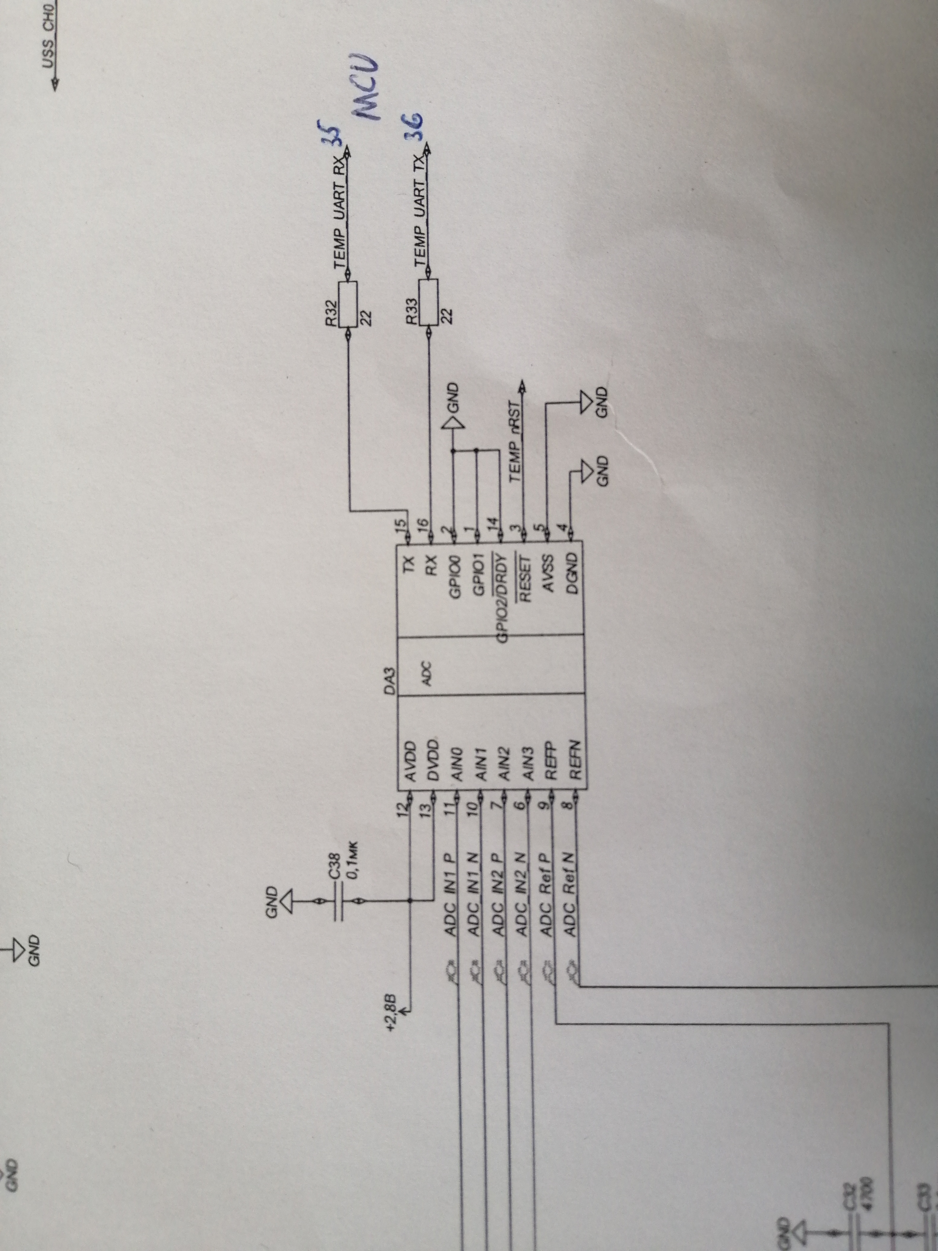
I have problem with reciving data from ADC`s register. The code may send commands to  ADS122U04 via UART from MCU. But when I use commands from datasheet to set registers or read they value happens nothing. The code placed lower.


#include <msp430.h>
#include <msp430fr6043.h>
#include <stdio.h>
#include <stdlib.h>

// ----------------- global variable ---------------------------------------------

unsigned int rcv;

// ------------------ initialization -----------------------------------------------

void CS_init (void);
void UART_init(void);
void UART_transmit(void);

// -------------------- main ---------------------------------------------------

int main(void)
{
    WDTCTL = WDTPW | WDTHOLD;   // stop watchdog timer

    // Disable the GPIO power-on default high-impedance mode to activate
    // previously configured port settings
    PM5CTL0 &= ~LOCKLPM5;
    FRCTL0 = FRCTLPW | NWAITS_1;

    CS_init ();

    UART_init();

    UART_transmit();

}

// ------------------ functions -----------------------------------------------

void CS_init (void)
{
    CSCTL0_H = CSKEY_H;
    CSCTL1 = DCOFSEL_3 | DCORSEL;
    CSCTL2 = SELA__LFXTCLK | SELS__DCOCLK | SELM__DCOCLK;
    CSCTL3 = DIVA__1 | DIVS__1 | DIVM__1;
    CSCTL0_H = 0;
}

void UART_init(void)
{
    P4SEL0 |= BIT1 | BIT2;
    P4SEL1 |= BIT1 | BIT2; // It switch pins P4.1 and P4.2 in RX/TX mode

    UCA3CTLW0 = UCSWRST;                    // Put eUSCI in reset
    UCA3CTLW0 |= UCSSEL__SMCLK;             // CLK = SMCLK
    UCA3BRW = 54;                           // 8000000/16/9600
    UCA3MCTLW |= UCOS16 | UCBRF_1 | 0x4900;
    UCA3CTLW0 &= ~UCSWRST;                  // Initialize eUSCI
}

void UART_transmit(void)
{
    UCA3TXBUF = 0x55;
    while (!(UCA3IFG & UCTXIFG));
    UCA3TXBUF = 0x06;
    __delay_cycles(80);
//    }

    while (!(UCA3IFG & UCTXIFG));
    // Settings reg 2
    UCA3TXBUF = 0x55;
    while (!(UCA3IFG & UCTXIFG));
    UCA3TXBUF = 0x44;
    while (!(UCA3IFG & UCTXIFG));
    UCA3TXBUF = 0x40;
    // Recive reg 2
    while (!(UCA3IFG & UCTXIFG));
    UCA3TXBUF = 0x55;
    while (!(UCA3IFG & UCTXIFG));
    UCA3TXBUF = 0x24;
    while (!(UCA3IFG & UCTXIFG));
    while (!(UCA3IFG & UCRXIFG));
    rcv = UCA3RXBUF;

}


  • Hi user6244799,

    I don't see anything that would cause an issue in your code except for some potential timing violations.  Here are a few things to check:

    • Make sure that the RESET pin of the ADS122U04 is pulled high.
    • Your delay time is unclear and may not be long enough.  If I assume that one cycle is 1us, you need a minimum of 80us after the RESET command is decoded.  In your code you show a delay of 80 and if my assumption is correct this would wait 80us, but you to make sure that the command was completely transmitted and is not in a FIFO or still in the process of transmission.  The delay should come after the "while (!(UCA3IFG & UCTXIFG));" and not before.
    • If you have a logic analyzer, you should check the communication and verify that you are using the correct protocol.
    • If you don't have access to a logic analyzer then you should monitor the timing of the communication with an oscilloscope to make sure that none of the timing is being violated.

    Best regards,

    Bob B

  • I follow your advices and face problem.
    I checked RESET. It is pulled high. I write the reset command (0000011x) and after that go to the delay and reset signal didn`t fell down a bit like Figure 2 on 8 page. I think this problem like first written question.
    UART is setted 8-N-1 and  protocol`s things correct (It checked by compare register`s values and they parameters in datasheet`s register map). I don`t understand how properly check by an oscilloscope, but think by the datasheet is correct too.

  • I fixed delay`s value because it wasn`t right, but the problem remains

  • Hi user6244799,

    It is not easy to verify UART communication without using a protocol analyzer.  These analyzers are included with logic analyzer software.  It is difficult to determine what is being transferred with an oscilloscope, but what you can determine the time between transfers.  This method helps to verify that enough delay time is be sent between the RESET command and the next SYNC command.  Also, you can make sure that the micro is not transmitting at the same time as data is being sent back from the ADS122U04 as the communication is not full-duplex (you cannot send and receive at the same time.)  If RX/TX happens at the same time the ADS122U04 will stop communicating and will need a manual (toggle the RESET pin) or a power-on reset.

    Another consideration is the data you are receiving could be from a FIFO buffer.  If that is the case, you need to make sure that the data you are reading from the RX buffer is the data being transferred from the last register read request and not some previous data in the buffer.

    Best regards,

    Bob B 

  • Could you suggest an analyzer for ADS122U04 or MSP430? When I surfed internet I didn`t found an analyzer (CCS haven`t it and the device haven`t third-party app for this)

    I watched sending signals in the oscilloscope. TX Code was put  in loop. And the data is displayed from microcontroller`s and ADC`s feet.

  • Hi user6244799,

    Can you send me a schematic?  Make sure that TX from the micro goes to RX pin of the ADS122U04 and TX from the ADS122U04 goes to the RX pin of the micro.

    I reread the previous post you sent, and I didn't fully answer the questions.  Regarding RESET, there are two methods to reset the device.  One method is to toggle the RESET pin.  In this case the micro GPIO would be used to toggle the state of the pin to place the device into a RESET condition.  If this pin is not used for this purpose, then the pin must be externally pulled high.  The second method is to use the RESET command.  The command will have no effect on the logic state of the RESET pin.  Figure 2 in the ADS122U04 datasheet is only showing the timing.

    As far as logic analyzers I typically use a Saleae, but I have also used a Digilent Analog Discovery kit.

    Best regards,

    Bob B

  • Hi user6244799,

    I have a couple more questions.  First, is the supply voltage level the same for both the micro and the ADS122U04?  Second question, are you using any isolation between the micro and the ADS122U04 or are the pins directly connected?

    Can you send me some oscilloscope shots of the communication for both the register write sequence and register read sequence showing both the TX and RX?  It would be helpful for me to see enough detail in the transfer of each byte so that I can compare to a known working solution.

    Best regards,

    Bob B

  • The track has been placed  between MCU and ADC feet.

    In this time i can not correct say about supply voltage level.

  • https://cloud.mail.ru/public/5CwR/3zds3Bic6
    This reference have a fild with pictures of an oscilloscope. The First shot is TX, the second one is RX, the third one is the default position of oscilloscope line.

  • Hi user6244799,

    Unfortunately I am blocked from using cloud based file sharing.  Can you zip the images and attach to the post using the paperclip icon?

    Thanks,

    Bob B

  • Hi user6244799,

    From the scope shots there appears to be communication with respect to the TX  line.  Is this TX from the micro?  Which command is being sent?   I also see two traces.  Can you explain what the blue colored trace is?

    For the RX line I see no clocking at all, but rather just a straight line.  If the previous command was the register read command then some data should have clocked out of the ADS122U04.

    I still suspect that there may be a timing issue.  I would first attempt to not send the RESET command at the start of your program, and then instead of sending the register write, send the register read and see if some data comes out of the ADS122U04.  For the oscilloscope you may need to change the trigger from auto to a single trigger sequence to capture the data on the scope.

    Best regards,

    Bob B

  • I detected my mistake. It was the set of different little inaccuracies. At this time the code work correct as explain in datasheet.
    Thanks for your help.
    But I have one more question. I want to add in the code delays and don`t use delay-function. How do this by timers?     

  • Hi user6244799,

    Thanks for the update.  I'm glad to hear you are making progress.  There should be some examples available regarding the use of timers for the micro you are using by going to the resource explorer in CCS.  In MSP430Ware->Libraries->Driver Library->MSP430FR5xx_6xx->Example Projects you can find projects using Timer A or Timer B.

    What I would suggest doing is creating a global boolean variable to be used as a status flag.  Initially set this variable to false, then initialize your timer and when it overflows, use a timer interrupt to set the status flag to true. 

    In your main loop, check for the status flag to be true, and if it is true go and read the conversion result.  When you are done reading the conversion result set the status flag back to false.

    Best regards,

    Bob B