This thread has been locked.

If you have a related question, please click the "Ask a related question" button in the top right corner. The newly created question will be automatically linked to this question.

ADS1282: Latency calculation

Part Number: ADS1282

Hi,

I'm trying to calculate the time from sample is captured until the DRDY# is asserted. The device operate in Read Data Continuous mode, 4.096MHz clock, 4000SPS, Continuous SYNC mode, Linear phase,  Sinc + LPF filter and HPF disabled (FILTR[1:0] = 10).

How do we calculate the delay through the pipe line?

Thanks in advance!

  • Hi Mikael,

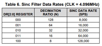
    The ADS1282 is a Delta-Sigma ADC that oversamples the input signal and then decimates the data in the digital filter stage. The programmable data rate determines the filter's decimation ratio:

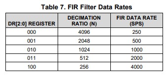
    Therefore, there isn't really a clear period between a single data capture and /DRDY going low. However, if you're asking about the pipeline delay from the start of data capture to /DRDY going low ("settling time"), or the time period between /DRDY falling edges ("data rate") you can calculate these from the equations shown in Table 10 and Table 35 of the ADS1282 datasheet. For the nominal 4.096 MHZ fCLK frequency, these times are:

  • Hi Chris,

    and thanks for always answering prompt and exact!

    However, I'm not sure we understand how "settling time" is defined. I made some tests and found that the actual latency in the ADC is between 6.9ms and 7.1ms at 4000samples/s - unless our timestamps are wrong.

    I use the 1PPS (that we use to synchronize all ADCs) fed via a simple LP filter to keep rise time below nyquist. We have a sample rate of 4000 and the input to the ADC looks like this (Yellow is 1PPS, blue is signal fed to ADC):

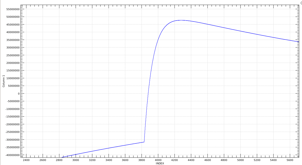
     The recorded signal in the ADC looks like this:

    When we calculate the start time of the positive edge (using our time stamped sample data), we se a delay of about 6.9ms and 7.1ms, which corresponds to the measured latency from the data hits the ADC until DRDY is asserted and the data is read out and time stamped.

    So, I wonder: have we misunderstood the term "settling time", is the table wrong, or are we doing something wrong with the timestamps?

    Thanks in advance!

    Mike

  • Hi Mike,

    If I understand correctly, you have the ADS1282 continuously converting and then you provide a kind of step input and observe the response of the output, which is lagging by about 7 ms.

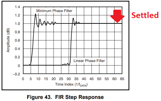
    I think what you are seeing is the group delay. When you apply a step input to the FIR filter you will see the following response:

    The settling time of the ADS1282 FIR filter is about 62 conversion periods. You can think of this filter as having 62 taps and so the settling time is how long it takes for a step input to fully propagate through all of the filter taps. The group delay on the other hand is about 32 conversion periods or roughly 1/2 of the setting time for the linear phase filter (this seems to correspond well with the 15ms settling time of the 4 kSPS FIR filter). While the output step is observed much sooner, the final settled values comes much later.

    The scale of the above plot can be a bit misleading since it appears like the filter has settled soon after the group delay; however, keep in mind that the output data is 31-bits wide (1 LSB can be less than 1 nV depending on the reference voltage and PGA gain), so the ringing continues beyond what is visible in the above plot.