This thread has been locked.

If you have a related question, please click the "Ask a related question" button in the top right corner. The newly created question will be automatically linked to this question.

TPL0401A-10-Q1: Application circuit

Part Number: TPL0401A-10-Q1

Hi Sir,

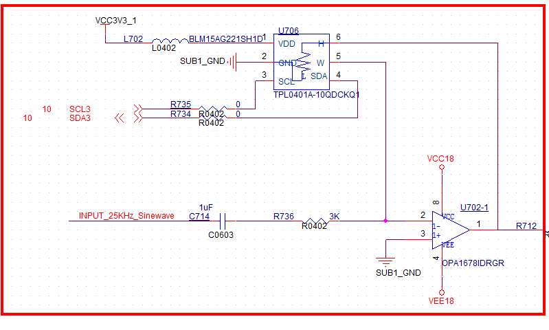
The application circuit is for OPAMP gain tuning. Please help to check if the application circuit of TPL0401 is suitable.

Thanks,

Roger
  • Hi,

    Circuit configuration looks ok. One key thing to consider the amplitude of the sine wave signals which you have not mentioned in the schematics above.

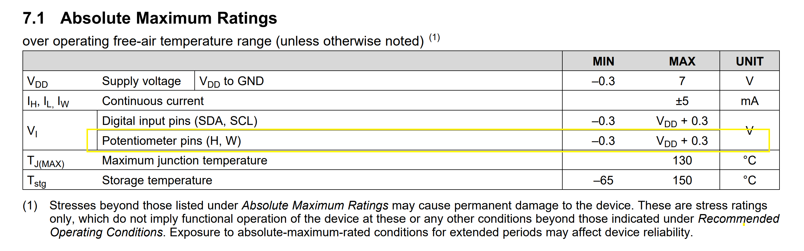
    Please be careful about the voltage at H and W terminal. It cannot be more than VDD + 0.3V, where VDD is your potentiometer supply

    Looking at the supply voltage of op amp, I assume your amplitude will be greater than +/-3.6V, in which case this circuit will not work. 

    Regards,

    AK

  • Hi AK,

    Thank you so much.

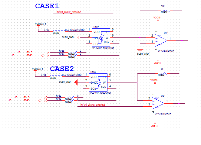
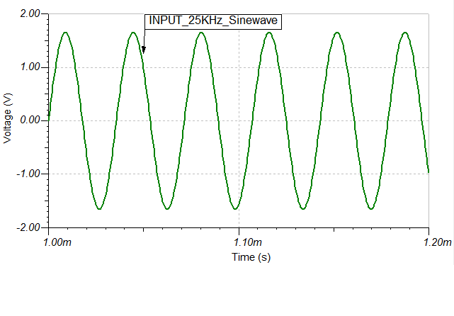
    The following are application circuit of case1 &2 and input waveform. Please help to review it.

    Regards,

    Roger

  • Hi Roger,

    In the first scheme, your circuit is inverting amplifier, for which your W terminal will be at virtual ground. H terminal sees the full swing of the input which around +/-1.65V. If you see the datasheet spec for TPL, H  terminal cannot go below 300mV. so you are violating this condition. So this scheme wont work.

    Coming to the second case ( Non inverting amplifier ), W terminal will see the full swing of the input, so it violates the minimum voltage. So both schemes wont work. if you want to control the gain, I suggest adding a DC offset to the input and do the gain control.

    See the datasheet snippet below.

    Regards,

    AK

  • Hi AK,

    Got it. Thank you so much.

    Regards,

    Roger