This thread has been locked.

If you have a related question, please click the "Ask a related question" button in the top right corner. The newly created question will be automatically linked to this question.

ADS1248 Hardware problem

Other Parts Discussed in Thread: ADS1248

Hello,

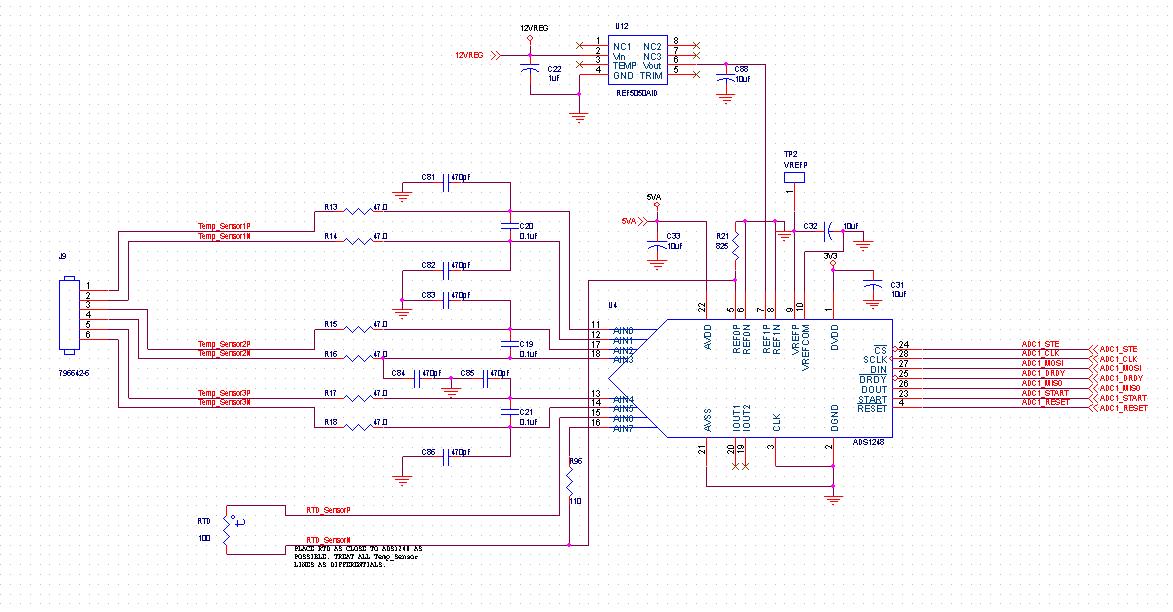
I'm looking for help in identifying an error with my design. My board works fine without the ADS1248, but once I solder the part on, the power supplies go out. 5V goes to 300mV, 3.3V goes to 0, and 12V goes to 7V. I checked the layout and it matches the pinout and topology of the schematic. I suspect there's a problem with my design.

Thank you for your help,

dlo

  • Dlo,

    Nothing is obvious in the schematic.  You might want to double check that the device is oriented on your board in the correct direction (not upside down).  Also double check to make sure that there is not a solder bridge between the power pins.

    Best regards,

    Bob B

  • Thanks Bob,

    I have gone through and checked what you suggested already. I was really hoping it was a glaring design mistake on the schematic.

    A bit more info on some testing I've done.

    _ Lifted DVDD and AVDD pins

    _ Removed R21

    _ Replaced the part with a new one.

    None of the step above helped. Only completely removing the part will the board behave like it should.


    Thank you,

    dlo


    Bob Benjamin said:

    Dlo,

    Nothing is obvious in the schematic.  You might want to double check that the device is oriented on your board in the correct direction (not upside down).  Also double check to make sure that there is not a solder bridge between the power pins.

    Best regards,

    Bob B


  • Dlo,

    Is it possible to send a picture of your layout?

    One other thing, I see that the ground symbols are all the same.  Is it a correct assumption on my part that all the grounds are tied together (3.3V, 5VA and 12VREG)?  I guess I'm most concerned about the 12VREG which drives the REF5050.  For example, if the 12VREG supply ground is at a different potential, it could actually be floating much higher above the device grounds.  You might want to check all the device inputs relative to one reference ground point on the device to see if you have something that is higher than it should be voltage wise.

    One other thing to note is that the REF5050 exceeds the maximum reference input voltage of AVDD-AVSS-1.  This is not what is causing your current issue, but you should use a different external reference voltage value.

    Best regards,

    Bob B

  • How are the pins from your microcontroller to the ADC configured? The DOUT and DRDY pins should input on the microcontroller side.

    Niki Pruis

  • Bob,

    Thank you for the suggestions. I've been lifting more pins and nothing changes. However after you suggested changing the REF5050 to REF5020 I noticed that when the reference regulator is absent, the unit runs fine. This leads me to believe that I have a design problem with how I'm setting the REF1P pin.


    On another note, to answer your question about ground. All ground are tied together, including the 12VREG supply.


    Thanks for your help.

  • Thanks for the suggestions Niki. All digital control pins are wired to the microcontroller. DOUT and DRDY are inputs to the microcontroller.