Because of the holidays, TI E2E™ design support forum responses will be delayed from Dec. 25 through Jan. 2. Thank you for your patience.

This thread has been locked.

If you have a related question, please click the "Ask a related question" button in the top right corner. The newly created question will be automatically linked to this question.

ADS1262: ADS1262

Part Number: ADS1262
Other Parts Discussed in Thread: REF5025

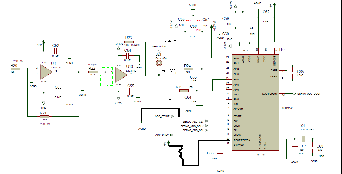
We are intending to measure +/- 2.5V signal. VDD is connected to +5V DGND to AGND. AVSS is connected to +2.5V AVDD is connected to -2.5V. AINCOM is connected to AGND. 

The reference is +2.5V connected to AIN0 and -2.5V connected to AIN1.

My question is is the above configuration correct to measure +/- 2.5V? The data sheet says you must connect AVSS and DGND toghther. But in my case AVDD is -2.5V and DGND is connected to AGND.

Thanks in advance.

Anuja

  • HI Anuja,

    Can you draw a picture of your setup and post it here? You mention "VDD" and "AGND", neither of which are valid pins on the ADS1262, so I want to make sure you have the correct connections.

    Also, please note that connecting +2.5V to REFPx and -2.5V to REFNx gives you a 5V reference voltage, whereas you really only need a 2.5V reference in this case. You could use the ADC's internal 2.5V reference for this purpose, or something like a REF5025. You also want to make sure that there is some margin on the input signal compared to the reference so you don't provide a signal that is greater than full-scale.

    -Bryan

  • Hi Anuja,

    Your last post is empty, I assume you tried to attach an image? Can you please reattach?

    -Bryan

  • Hi Bryan,

    Can you see the schematic screenshot now?

    Thank you,

    Anuja

  • Hi Anuja,

    Yes, this worked, thanks

    The connections look correct for the configuration you outlined (+/-2.5V input, +/-2.5V AVDD, +5V VREF +5V DVDD). Also, as I noted in my previous thread, connecting +2.5V to REFPx and -2.5V to REFNx gives you a 5V reference voltage, whereas you really only need a 2.5V reference in this case. You could use the ADC's internal 2.5V reference for this purpose, or something like a REF5025. You also want to make sure that there is some margin on the input signal compared to the reference so you don't provide a signal that is greater than full-scale

    I also could not see what the value of R22 is, but please make sure this value is sufficient to attenuate the input signal coming from the input amplifier (U8). I assume it is, but just wanted to clarify since R22 does not have a value assigned in the image you sent.

    If you have additional questions about your system, please start a new thread and we will be able to support you.

    -Bryan