This thread has been locked.

If you have a related question, please click the "Ask a related question" button in the top right corner. The newly created question will be automatically linked to this question.

ADS1299: DRDY pulses stop coming or the data is zero

Part Number: ADS1299

Hi,

I use the ADS1299 with an STM32F446 microcontroller DRDY pulses of the ADS1299 usually stop after a few measurements. If the pulses keep going, then the data is constant zero on all the eight channels after the few nonzero values. The SPI settings seem to be good because I can write and read the registers, and I can turn on the internal reference. If I measure the internal temperature sensor, then the new data stops coming after two cycles. The temperature reading seems legit because it measures about 28°C. I read out 27 bytes in every cycle. The SPI's frequency is 1.40625 Mbits/s. The ADS1299's datarate is the default 250 SPS. My registers are the following:
ID:00111110 -> 0x3e
CONFIG1:10010110 -> 0x96
CONFIG2:11010000 -> 0xd0
CONFIG3:11100000 -> 0xe0
LOFF:00000000 -> 0x00
CH1SET:00000101 -> 0x05
CH2SET:00000101 -> 0x05
CH3SET:00000101 -> 0x05
CH4SET:00000101 -> 0x05
CH5SET:00000101 -> 0x05
CH6SET:00000101 -> 0x05
CH7SET:00000101 -> 0x05
CH8SET:00000101 -> 0x05
BIAS_SENSP:00000000 -> 0x00
BIAS_SENSN:00000000 -> 0x00
LOFF_SENSP:00000000 -> 0x00
LOFF_SENSN:00000000 -> 0x00
LOFF_FLIP:00000000 -> 0x00
LOFF_STATP:00000000 -> 0x00
LOFF_STATN:00000000 -> 0x00
GPIO:00001111 -> 0x0f
MISC1:00000000 -> 0x00
MISC2:00000000 -> 0x00
CONFIG4:00000000 -> 0x00

I used a Picoscope oscilloscope to measure the signals. It is capable only to measure 2 channels.
The CS and clock signals:

The DRDY and the CS signals:

The DIN and the clock signals:
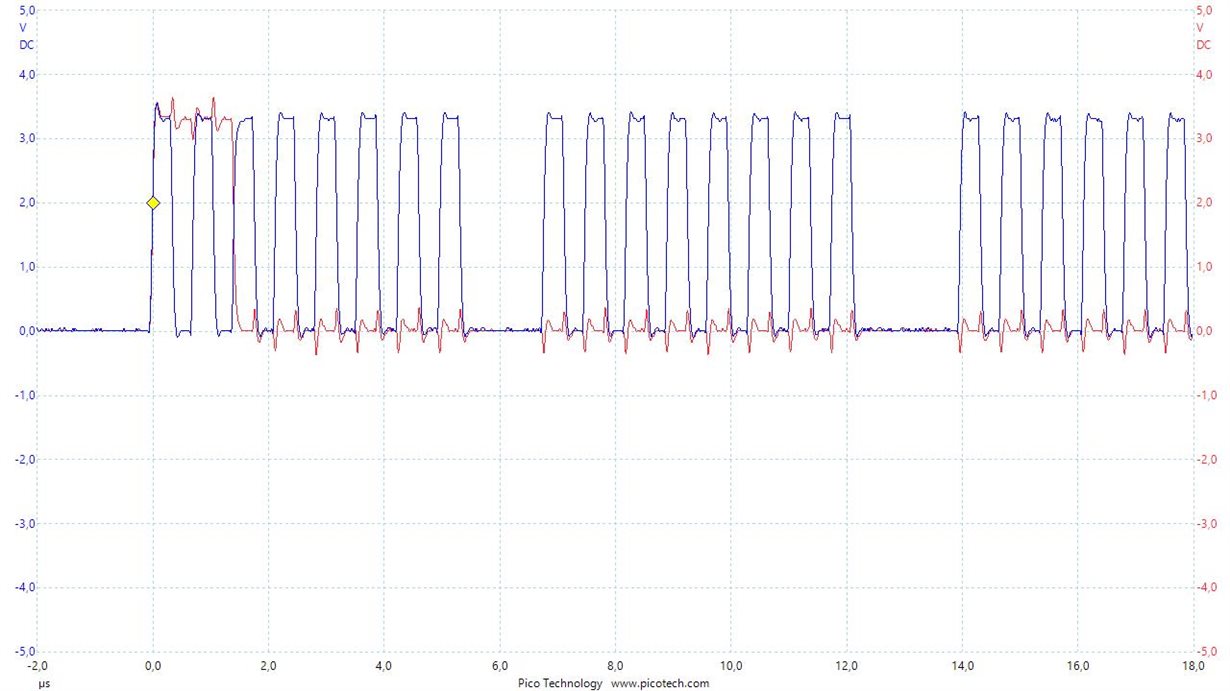
The DRDY and the clock signals:

I would like to ask your help to solve the measurement read problem. The forum posts about this IC helped me a lot to get to this point, but now I can not find the solution there.

Best regards,
Istvan

  • Hello Istvan,

    Can you please follow the procedure outlined in Figure 67 (section 10.1.2)  in the datasheet to configure the device in a basic state and capture data?

  • Hello Praveen,

    I started with that diagram. DRDY stops this way too. I think that I have done everything according to that diagram at power-up. If you see anything strange on the pictures I attached to my previous post, let me know about that. Do you know any reason, why the DRDY can stop if I don't reset the IC and the power is stable? On a few occasions, DRDY keeps running, but the data turns to zero after a couple of readings.  Is it possible the rework solder station overheated the IC during soldering? This is the second version of my PCBs I test the same IC.

    Best regards,
    Istvan

  • Hi Istvan,

    Are you putting the device in RDATAC mode for this test? Can you capture more DRDY pulse on your scope together with the START, DOUT, and SCLK signals? Please make sure you set the START pin high for normal conversion. If the START pin is low and the START command has not been sent, then the device doesn't issue a DRDY signal (conversions are halted).

    Thanks.

    -TC  

  • Hi TC,


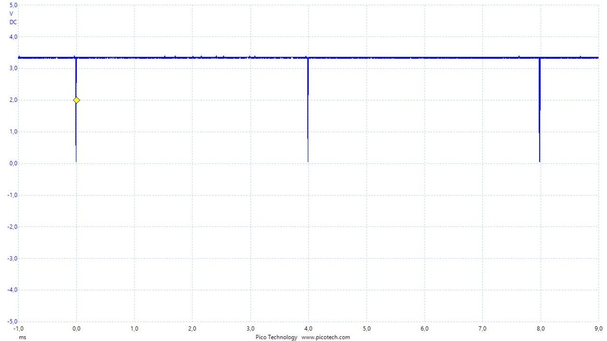
    Of course, I use the RDATAC mode. DRDY signal:

    DRDY and START signal:

    DRDY and DOUT signal:

    DRDY and SCLK signal:


    I use the start pin, not the start command. I noticed some strange behavior. If I don't read out the registers, then the DRDY keeps going on without stopping, but I get only zero values. That is a partial win. If I print out the registers, then I get several non-zero values, then the DRDY stops. The channels are connected to the internal test signal generator.

    Best regards,
    Istvan

  • Hi Istvan,

    Everything looks correct on your scope plots. All signals are behaving exactly like it is supposed to be for the device. When you are reading the device registers, you have to issue an SDATAC command. If you want to continue with reading data after register read, then you have to issue the RDATAC command to enable conversion data output. 

    Thanks.

    -TC

  • Dear TCT,

    My problem is solved. I changed the HAL_SPI_Receive function to HAL_SPI_TransmitReceive and sent out 0 values while the microcontroller is reading the data.

    Best Regards,

    Istvan