Other Parts Discussed in Thread: AMC1210,
Hi team,
I was using AMC1305EVM and AMC1210EVM for testing and found some questions that puzzled me.
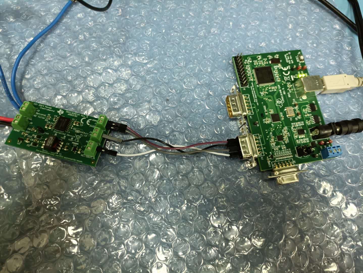
The test circuit diagram is shown in the figure:
The input of AMC1305 is 200mv sine wave,Through the AMC1210 software settings, as shown in the figure below:
The result is this:
I am very puzzled why there is such an image. According to my understanding, it should be a sine wave output. Is it a problem with my settings, or something else?
I also tested the output graph of sin3:
May I ask what is the problem? Can you give me some suggestions, thank you!


