This thread has been locked.

If you have a related question, please click the "Ask a related question" button in the top right corner. The newly created question will be automatically linked to this question.

ADS1232: Longtime ADS1232 temperature and weight data register

Part Number: ADS1232

Hi,

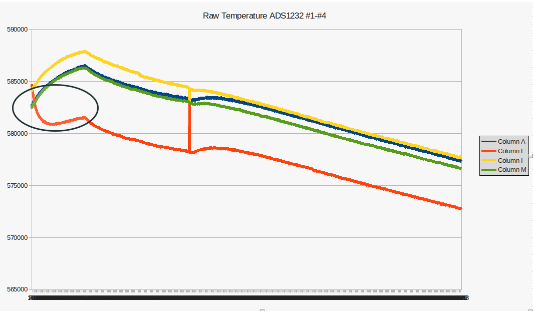
I'm testing four ADS1232 weight scales simultaneously and I have some doubts about the results obtained after a 15 hours of registered data (sample-time: 1 second). Here's the graph for the raw temperature of the four scales (#1:blue, #2:red, #3:yellow, #4:green)

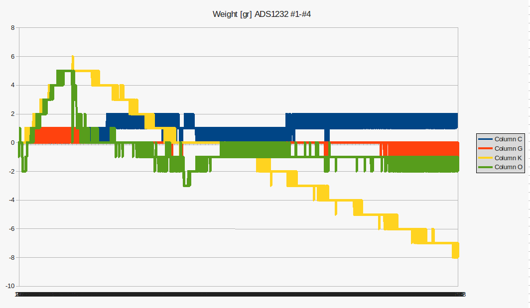
And here's the graph of the weight in grams (zero adjusted and scaled)

The peak that can be observed in the first graph does not worry me since it is probably due to some interference. However other behaviors are strange to me:

  • Temperature versus time on scales # 1, # 3, and # 4 seem to follow the same trend, but scale # 2 has an inverse effect on the first recordings. What could be the cause?
  • The variation of the weight recorded in scales # 1 and # 2 seems adequate to me, but the measurement in scale # 3 rises to 5gr and then falls to -8gr. It seems excessive to me.
  • On the other hand, scale # 4 seems to follow the same initial slope as scale # 3 but from 5g it drops steeply to follow the same trend as scales # 1 and # 2.
Can someone help me understand this behavior?

thanks in advance,
gaston

  • Hi Gaston,

    It would be helpful to see a schematic and to some the characteristics of the load cell you are using.  It is easier for me to evaluate what is going on when I don't see the result following the computation.  In other words raw conversion codes is what I would prefer to see.  But I understand in that you are attempting to evaluate your system as it would be used.

    • Temperature versus time on scales # 1, # 3, and # 4 seem to follow the same trend, but scale # 2 has an inverse effect on the first recordings. What could be the cause? [Bob] I do not have your schematic so I can only speculate.  The temperature measurement from the scale #2 does eventually follow the same trend as the others.   It is also interesting that the trend most closely matches the scale #1 although there is an offset.  It is also interesting that in the recorded weight test these devices also match closely.  So for #2, there could be differences in self-heating compared to the others or there could be differences in air currents.  Another possibility is there could be some reference settling as the measurement is not ratiometric. It is also possible that there is some offset and gain drift.  It is unclear as to whether or not you have issued a self-offset calibration.  It is possible that #2 has different offset characteristics compared to the other devices.
    • The variation of the weight recorded in scales # 1 and # 2 seems adequate to me, but the measurement in scale # 3 rises to 5gr and then falls to -8gr. It seems excessive to me. [Bob] Here it would be nice to know how many codes are actually shifting relative to the full-scale range.  Scale #3 appears to be following would might be the offset drift relative to the temperature drift shown in the first graph.  The drift characteristics can differ some from device to device.  One recommended method to account for offset drift is to issue periodic self-offset calibrations.
    • On the other hand, scale # 4 seems to follow the same initial slope as scale # 3 but from 5g it drops steeply to follow the same trend as scales # 1 and # 2. [Bob] Scale #4 does appear to become more stable in time.  I would investigate and list the potential differences in the measurements from scale to scale.  I assume that the scales/ADCs are in close proximity to each other.  When I have conducted similar tests I have found that with boards in the same lab with a fairly constant temperature, that there can be a significant difference in the drift results when comparing devices.  Consider too that the load cell itself can also drift.  So what I do is to isolate the thermal effects as much as possible by covering the PCBs (with a box or bag) to limit the air currents.  For example, consider that a power supply or computer may have a fan that operates near the test setup.  The air currents will be different even inches (or centimeters) away from the source, and the distribution of convection currents around the lab will be quite different as well over these short distances.  So to adequately compare the setups, they should be in as identical a thermal condition as possible, and the self-offset calibration should be issued after the reference has stabilized.
  • Hi Bob,

    Thank you very much for your answer. There is no problem sharing this information with you and understanding what is going on. Currently, here's the involved schematic and ADS1232 layout.

    More things:

    • VIN is provided from USB-5V and AVDD is configured to +3.3V
    • Weight data rate is 10SPS
    • 16-sample Moving Average calculation is used. Registered weight data is retrieved every 1 second
    • Temperature data is obtained every 10 seconds after a offset calibration procedure. Here's the detailed steps every 10 seconds:
      1. offset calibration
      2. Set the channel for the temperature and wait for 5 samples for the ADS to stabilize and return the last one
      3. Set the channel for the weight and wait for 5 samples for the ADS to stabilize and return the last one
      4. Perform Move Average filter
    • The rest of the time point 3. and point 4. are repeated (but for point 3. there is no waiting time for 5 samples)

    Do you see something strange or that does not quite fit?

    regards,
    gaston

  • Bob, I forgot to comment on the topic related to load cells and the setup of the scales. In the first case, it is a question of load cells with very unreliable information but that, let's say, they 'measure'. The sensor is a 5Kg strain half-bridge resistors that it can be configured as a 5kg x 4 = 20Kg full bridge load cell as follows:

    Regarding the work environment, let me tell you that the tests have been carried out in a closed office during the afternoon and at night from an initial temperature of 25ºC (aprox.). In the previous registered data graph, it can be seen how the temperature is decreasing since we do not have room temperature regulation. The setup used corresponds to 4 full scales connected to an RS485 bus plus a raspberyPI that query the data  weight-temperature every second and saving it in a csv file.

    regards,
    gaston

  • Hi Gaston,

    Your setup is quite straightforward. I do think you need to consider the drift of the load cells themselves. It looks like it would be difficult, but it would be interesting to repeat the experiment by replacing the load cells with a fixed resistor bridge using low temperature coefficient precision resistors to determine how much the ADC varies over time using the same measurement process.

    One further question, are you applying additional weight to the platform?  Or are you just weighing the plexiglass platform itself?

    If I understand the layout correctly you are using a 2-layer PCB.  Take a look at the following information put together from one of my colleagues.

    https://e2e.ti.com/support/data-converters/f/73/p/755516/2790926

    I would highly recommend using 100nF supply bypass caps at the supply pins of the ADS1232.  I would also recommend placing a cap across the reference input pins using a minimum of 100nF. 

    It is unclear if you are using any analog input filtering.  The analog input filter will help decrease any external noise and also prevent aliasing.  The IN+ and IN- signals are running on both sides of the ADS1232.  These lines will carry very small signals and as they run along the edge of the board will act like an antenna to external noise sources.  These signal lines should contain a good ground area underneath and run as direct as possible to the ADS1232.

    I don't see anything else that would create an odd drift pattern, but like I mentioned earlier it would be good to get a baseline of the ADS1232 by itself with limited impact of the load cell to determine what requires further attention.

    Best regards,

    Bob B

  • Hi Bob,

    Bob Benjamin said:
    Your setup is quite straightforward. I do think you need to consider the drift of the load cells themselves. It looks like it would be difficult, but it would be interesting to repeat the experiment by replacing the load cells with a fixed resistor bridge using low temperature coefficient precision resistors to determine how much the ADC varies over time using the same measurement process.

    Good idea. It won't take me too long to do this test.

    One further question, are you applying additional weight to the platform?  Or are you just weighing the plexiglass platform itself?

    I'm just weighing the plexiglass platform itself.

    Bob Benjamin said:
    It is unclear if you are using any analog input filtering. 

    No, I have not used any input filter.

    After reading the rest of your comments I see clearly that my design is not very refined. In this scenario, it will be difficult to determine the causes of the observed drifts. Therefore, I will need to take some actions to reduce uncertainties. Thanks for your suggestions. They will be very useful to me to continue advancing with the project.

    regards,
    gaston