This thread has been locked.

If you have a related question, please click the "Ask a related question" button in the top right corner. The newly created question will be automatically linked to this question.

DAC60501: DAC60501 Not Working Per Datasheet

Part Number: DAC60501

Dear Support:

I have a DAC60501 on a PCB that I am bringing up and running into an issue with the device not behaving per the datasheet.  I am using I2C to communicate with the device, and the values I am getting from the reading the registers upon power-up are not matching their default values.  For example, the DEVID register should read 0x2295 and instead I am reading 0x2195. The CONFIG register should read 0x0000 and instead I am reading 0x0200.  I have tried reading these registers before writing 0x000A to the TRIGGER register (performs a POR) and after writing this value of 0x000A to the TRIGGER register - still the same result.  In addition, upon reading the STATUS register, I am reading 0x0001 which has the REF-ALARM bit set indicating that the DAC output will be at zero volts as a result.  

However I measure the VREFIO pin and it measure 2.5V during this testing which indicates that the internal reference is working properly.  However when I write to the DAC register to output a voltage, the output remains at 0V no matter what value I write to the DAC register.  Do you know what I am doing wrong here and why these register reads are not matching per what the datasheet indicates that they should be?  Please advise.

Thanks,
Tim

  • Hi Tim,

    Let's start by looking at this REF-ALARM condition.  Is the voltage on VDD? If you are operating at low voltage (2.7V to 3.3V), then you will need to enable the reference divider (REF-DIV) to clear the alarm state.

    Thanks,

    Paul

  • Hey Paul:

    Thanks for responding over the weekend and your  accurate assessment - much appreciated.  I didn't realize that about needing to set the REF-DIV bit.  Yes, I do have the VDD @ 3.3V so you were right about me needing to set this bit and that indeed fix the problem.  I am able to write to the DAC register and get a corresponding output voltage that is accurate and per expectations.  However I am still seeing 0x2195 with the DeviceID register when per the datasheet, it should be 0x2295 and I am reading 0x0200 with the Configuration register when per the datasheet is 0x0000.  Do you know what is going on here?

    Thanks,
    Tim

  • Hi Tim,

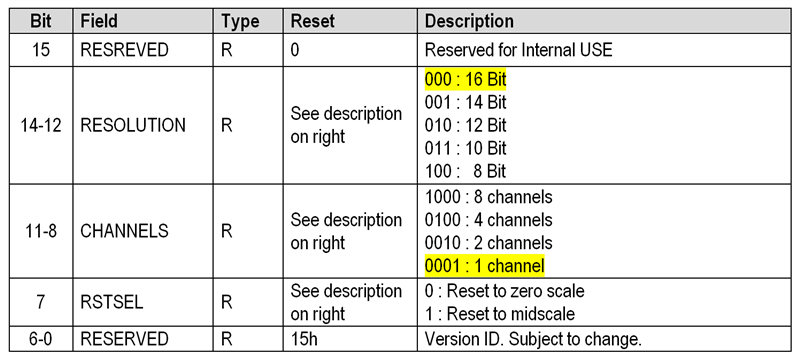
    Infact you are reading deviceID register correctly. There is a mistake in the datasheet. Please use the below table to decode the deviceID register.

    Coming back to CONFIG register, default you should read  0x0000.

    Regards,

    AK

  • Hey AK:

    Thanks for getting back with me over the weekend too!  Much appreciated.  Can you tell me where you are getting this information on the DEVID register?  This does now match with the datasheet that I have.  I am using document SBAS794D dated Feb 2020 which is the datasheet on this device - see below:

    So do you know why I would be reading 0x0200 from the Config register?

    Thanks,
    Tim

  • Hey AK:

    I see that my snippet from the datasheet didn't come through.  Oh well, it doesn't matter since you informed me that it is an error.  So I assume I have the right document.  Your thoughts on the Config register though?

    Thanks,
    Tim

  • Hi,

    In order to attach picture in e2e, you need to use the attach button in  tool bar . Copy/Paste will not work.

    Now coming back to CONFIG register, are you reading 0x0000 immediately after power up ? On power up it should be 0x0000. Since you are reading DEVICE_ID right, i don't suspect any issue with your SPI frame.

    As a debug, can you write 0x0000, and try to read back?

    Regards,

    AK

  • Hey AK:

    Yes, that is what I did - wrote 0 and it comes back as 0x0200.  Also tried reading this after power-up and it also reads back as 0x0200.  All other registers are coming back per expectations and per the datasheet - except for the DEVID register which per your correction in the datasheet is now correct.  :-)

    I assume this is not a big deal since the device is working properly now, but would like to know what is going on with this Config register if this is in error or not.

    Thanks,
    Tim

  • … and thanks for the tip on the cut-and-paste problem with this posting GUI - didn't realize that.

    Thanks,
    Tim

  • Hi,

    Let me check this with design document and gets back to you ASAP.

    Regards,

    AK

  • Hi,

    I got an update from the design document, and CONFIG should be 0x0000 after power up.

    Please check your read frame.

    Regards,

    AK

  • Hey AK:

    Thanks for getting back with me on this.  Oh I have checked many times - it is 0x0200 that comes back.  I have another board that I can test.  I will do the same with it and capture the I2C transaction with my logic analyzer and send to you.  Will be later today.

    Thanks,
    Tim

  • Hi,

    I ran this issue through one of our digital designer who was in charge of this device. Your observation is correct, CONFIG register is 0x0200 by default.

    We will update the product datasheet, sorry for the inconvenience.

    Regards,

    AK

  • Thanks AK for the follow-up and answering my questions - all is well on my end now.  Good to know that the chip is working per expectations.

    Thanks,
    Tim