Other Parts Discussed in Thread: ADS1299
Hi everyone!
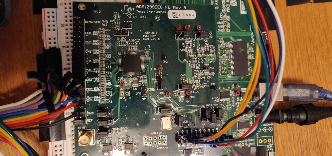
I am trying to test the reading of an ECG signal with the ADS1299EEGFE kit. The electrodes are connected as the following:
- LA (left arm) to the AIN1P
- RA (right arm) to the AIN1N
- RLD (right leg drive) to the pin JP25.2
The overall jumpers connections on the board are set as default:
The register map on the provided software:

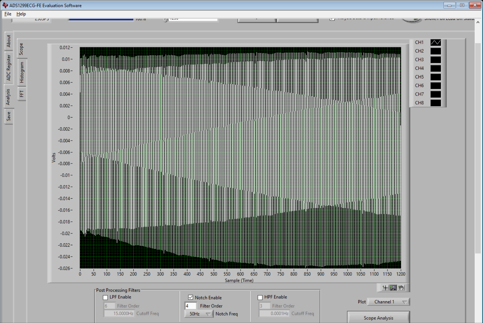
1250 samples of recording at 250 SPS without any type of filtering:

The previous signal acquisition with a 50Hz Notch filter (European standard power line frequency):
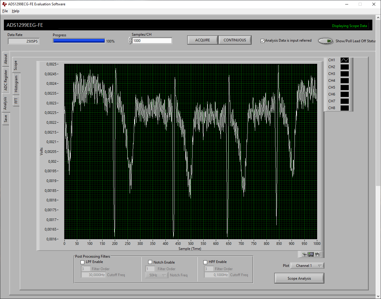
Only with a low pass filter with cutoff frequency at 15Hz and a 6 order I can barely see an ECG shape. I have tried different combination of cutoff and filter's order, but the result more or less remains the same unless more smoothing or stretching of the signal:

The FFT analysis suggests that the main frequencies are at 50Hz and 100Hz:

That said, I was wondering if I had some settings wrong, because the only noise I could imagine and visualize is the power line frequency of 50Hz (as confirmed by the previous FFT analysis).
If you have any kind of suggestions on what I am doing wrong please let me know.
Thank you very much in advance for your time!
Best Regards,
Manuel