This thread has been locked.

If you have a related question, please click the "Ask a related question" button in the top right corner. The newly created question will be automatically linked to this question.

RE:ADS1230 How to retrieve data and convert to weight

Other Parts Discussed in Thread: ADS1230

Hi Bob,

thank you for helping out.

We have a problem that Data Ready (DRDY/DOUT) pin stays always high for some reason.

Design is based on reference design which is copy pasted for ADS1230REF Users Guide (2007) which contains schematic.

What could possibly be wrong that ADS doesn't at least generates info on that pin.

BR,

Nikola.

  • Hi Nikola,

    You need to make sure that there are no pins floating or unconnected on the ADS1230.  CLKIN must be set low to use the internal oscillator or an external clock must be provided.  SCLK must be low, and PDWN must be high for the ADS1230 to operate.  Set the SPEED and GAIN pins to the desired operation.  Both AVDD and DVDD must be at the nominal operating voltages.  I would also recommend that if you are using different voltages for AVDD and DVDD, that the AGND and DGND be tied together.

    There is also a requirement that PDWN be held low for at least 10us after power is applied.  See figure 30 on page 19 of the ADS1230 datasheet.  If at all possible I would suggest controlling the PDWN pin with a GPIO pin from the micro instead of using the circuit of figure 31.  In this way the firmware can control the timing of the PDWN pin and will also allow you to reset the device by pulsing the PDWN pin.  I would also recommend pulsing the PDWN pin after power up to ensure the device is internally configured properly.  Pulsing the PDWN pin will act like a device reset.

    Best regards,

    Bob B

  • Hi Bob,

    BIG thank you, it seems that your text has brought us to the point and also helped to discover some more issues.

    Are there any complete examples and hardware (design files and real world PCB which we can buy) that you know from TI would be good starting point to get?

    BR,

    Nikola.

  • Hi Bob,

    It seems that we have somehow got to the point that we read KG but it seems with lot of error.

    Current situation is that we read 20bit value and have 3mV/V with 250Kg Load cell , excitation voltage 5V and gain 64.

    Could you please help at least with some snippet or something how to get from that to KG values?

    Thank you in advance.

    BR,

    Nikola.

  • Hi Nikola,

    If you are using the same voltage for both the excitation and for the ADS1230 reference voltage, then the measurement  becomes ratiometric whereby the output code relates to the ratio of the scale output relative to the excitation.  The full-scale range of the ADC is greater than the full-scale output of the load cell, so only a portion of the dynamic range will be used at a gain of 64.  I would suggest using a gain of 128.  For the ADS1230 to measure the input correctly, the analog supply should be 5V and the reference should also be 5V to make sure that the analog input is within the input range of the ADS1230.  The excitation of a bridge will set the common-mode of the signal output at 1/2 of the excitation voltage (2.5V for a 5V excitation).

    For now let's look at the expected output at a gain of 64.  The full-scale range (FSR) of the ADS1230 is +/- 0.5*Vref / Gain.  For a 5V Vref, the FSR is +/- 0.5*5 / 64 or +/- 39mV.  If you use a gain of 128, the FSR is +/- 19.5mV.

    The maximum output of the load cell for 3mV/V excitation will be 3mV * 5V, or 15mV.  So either a gain of 64 or 128 will work with the maximum dynamic range at 128.

    After your system is powered and the supplies have stabilized, you should issue a Self-Calibration for the ADS1230 to remove offset error of the ADS1230.  The calibration is explained on page 16 of the ADS1230 datasheet.  This is accomplished by sending a minimum of 26 SCLKs in the format shown in figure 27.  Unless you are bit-banging the output, the easiest method would be to issue 4 bytes worth of SCLKs to initiate the self-offset calibration.  So the process would be:

    1. Power up the ADS1230.
    2. Wait for all supplies to settle to the nominal operating voltages.
    3. Wait for the first conversion to complete.
    4. Read the data and start the self-offset calibration by issuing a minimum of 26 SCLKs.
    5. Next falling edge of DOUT/DRDY will have completed the self-calibration process.

    You should also do a 2-point calibration of the system as a minimum.  The first point is the zero point, or no load on the load cell.  The second point is to set the load cell at or near maximum output so you can determine the gain slope of the system.

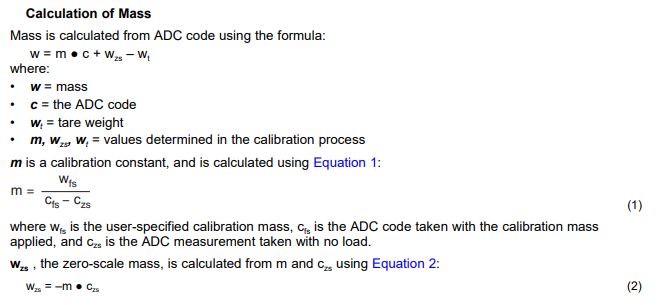
    The following information is in the ADS1230REF user's guide in section 2.1.1.

    Your code should reflect the above process. 

    1. After the self-offset calibration determine the output code for no weight applied to the load cell which becomes (Czs) and store to a variable.
    2. Apply a calibrated weight for the full-scale output of the measurement.  This may not necessarily be the maximum weight of the load cell capability. Store the output code for the full-scale range of the scale.  The code stored is Cfs or the code full-scale.
    3. Determine the calibration constant 'm' by using formula 1.  The Wfs or weight full-scale is the calibrated weight value used to determine Cfs.  The constant 'm' is the ratio of the number of codes for the weight range to full-scale.  Store the ratio as a floating point value.
    4. Using equation 2 you can determine the load cell offset by weight and determine the weight zero scale (Wzs) and store as a floating point value.
    5. You can add a platform or tray and 'tare' the scale to be able to remove the weight from the actual measurement and store as a floating point value.  Wt = m*Ct + Wzs
    6. Apply a weight to be evaluated and determine by using 'm' times the code returned from the ADC, then adding the offset Wzs (remember this is already a negative value from equation 2) and then subtracting the 'tare' value Wt.

    I hope that is enough to get you started.  Initially you can determine the values by hand calculation prior to writing any code.  Let me know what additional information may be helpful. 

    Giving me the ADC code results for the applied weight would be helpful.  Also, if you are having issues with communication, please send me any scope or logic analyzer shots of the communication.  A schematic would be helpful as well.

    Best regards,

    Bob B

  • Hi Bob,

    from complete frustration to working and completely running solution only and solely because your effort.

    I don't know how to thank you, hope this communication stays for long so that others can get real and valuable information.

    BR,

    Nikola.

  • Hi Nikola,

    I'm glad that I could be of some help.  I split the thread and renamed to make searching a little easier.  If you have any more questions, please feel free to start a new thread.

    Best regards,

    Bob B