This thread has been locked.

If you have a related question, please click the "Ask a related question" button in the top right corner. The newly created question will be automatically linked to this question.

ADS54J40: Some ADS54J40 parts show regular offset jumps

Part Number: ADS54J40

Hi,

I hope that someone can help me with this issue we recently discovered.

We're using ADS54J40 in a DC-coupled design. We use only channel A, everything of channel B that we could disable is disabled. We have disabled VCM compensation (master page reg 0x4F = 0x01) and completely bypassed the interleaving offset correction (reg 0x6068 = 0x06)

In most of our modules this works very well (~75%, not a lot of statistics yet). Stable DC inputs give stable raw ADC outputs, with just a few LSB of noise.

However, in some modules we see weird offset jumps. It's a very regular pattern, the same pattern for at least 2 different modules: every 1.6seconds there's a 40ms period where the ADC output jumps.

Even weirder is that this only seems to occur when the ADC diff input voltage is in the range of ~+0.53V to +0.89V. Outside this voltage range we don’t observe the jumps.

Table below shows the 4 sub-ADC channel outputs for a clean DC +0.756V differential input at the ADC.

Sub-ADC #2 doesn’t show any jump, #1 and #3 show a +61LSB jump, and #4 shows a +100LSB jump:

NORMAL

JUMP

diff

ADC raw LSB

subADC1

6602

6665

62

subADC2

6525

6525

1

subADC3

6446

6508

61

subADC4

6524

6624

101

average

6524

6580

56


We have ruled out a lot of external factors that could cause this jump, and now we’ve come so far that we think it’s an artefact caused by something inside the ADC.

Did someone observe this behavior before? Is there a solution for this? It’s really affecting the performance of our module.

Best regards,

Paul

  • Paul,

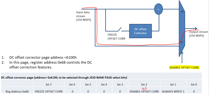
    Try freezing or bypassing the DC offset correction. More info regarding this can be found in section 9.1.4 of a soon to release revision of the ADS54J40 data sheet (attached).

    Regards,

    Jim

    SBAS714_ADS54J40 Filter2=2=TI PDF=en-us (10).pdf

  • Hi Jim,

    Thanks for your quick response. Also thanks for the updated (draft) datasheet.

    In my original message I indicated "[we]... completely bypassed the interleaving offset correction (reg 0x68 = 0x06)".

    A question now pops up in my mind: this control register controls all 4 sub-ADC corrections together, right? Or do all 4 sub-channels have their own individual DISABLE and FREEZE control?

    We already experimented with enabling the correction, just to see if the behavior was different, and it was (but still not OK). In our case (high DC value input) we think that all 4 DC correction values clipped to their max limit.

    Anyway, we will do some additional tests by also freezing the offsets, and setting them to zero. But if your diagram below is correct, then I expect no effects from that, to be honest.

    Best regards,

    Paul

  • This picture seemed missing in previous post

  • Paul,

    This address takes care of all 4 ADC used by the channel. Try freezing the DC offset correction (not bypass).

    Regards,

    Jim

  • Hi Jim,

    I am a colleague of Paul. We have tried all settings regarding the DC offset correction, but this has no effect on the issue. 

    The draft datasheet you have shared helped us a lot, so thank you for that:

    We have found out that freezing and disabling the IL engine seems to prevent/solve the issue. But from only the datasheet we do not yet understand exactly how the IL engine is causing our issue.

    (Only Freezing the IL engine seems to introduce another effect, bigger pulses which repeat every ~17 seconds.)

    Does it make sense that our issue is caused by the IL engine? (for example considering the issue time periods (1.6s, for 40ms) vs inner workings of the IL engine?)

    Could you advice what settings we should use for the IL engine in our DC-coupled application, with long DC periods and short pulses?

    And would it be possible to have a call or something to discuss our questions regarding the draft datasheet?

    Further I had some side notes:

    • The draft datasheet contains a whole section double (for example Table 8-15 is on page 48 and 93)
    • The general register 4h seems to be a write-only W register (the datasheet indicates R/W) (probably also the case for 1h, 2h, 3h and 5h)

    Best regards,

    Antwan

  • Antwan,

    I am closing this post as we are taking this offline with you.

    Regards,

    Jim