This thread has been locked.

If you have a related question, please click the "Ask a related question" button in the top right corner. The newly created question will be automatically linked to this question.

ADS1261: Error in first ~30 values read after conversion start

Part Number: ADS1261

Bizarre question, but I'm new to this part: I'm evaluating the ADS1261 for use in a weigh scale application using the ADS1261EVM talking to a microcontroller (I disabled the EVM onboard micro).  I'm configuring for AC excitation driving four load cells in a bridge configuration, using the bridge excitation signals as the ADC references, taking data at 60 samples/second, Sinc3 filter, PGA gain of 128.  Because this needs to be a low-power application, I'm waking the ADC1261, taking 50-100 measurements in continuous mode, then putting the ADS1261 back to sleep for a while (I've done this both using the PWDN pin and writing bit 7 of the MODE3 register without seeing a difference in behavior).  The problem I'm seeing is that in the data I collect, the first sample is ~200 ADC counts too high, with each successive sample decreasing until values stabilize after about 25-30 samples are collected.  So for a temporary workaround, I have my software taking 80 data points and throwing away the first 30 so that I'm left with 50 good values.  Obviously, I don't want to do this.  Is there something I'm missing here?  I've been through the datasheet and can't find anything obvious about things needing a certain amount of time to stabilize, since I'm not using the internal reference.  Does the Sinc filter need to precharge with data before its output is good?

  • Point to add: This is only being seen when I sleep/wake the ADS1261 with PWDN or the MODE3 register.  If I leave the ADS1261 powered-up all the time, the data collected is good from sample #1.

  • Hi Brian,

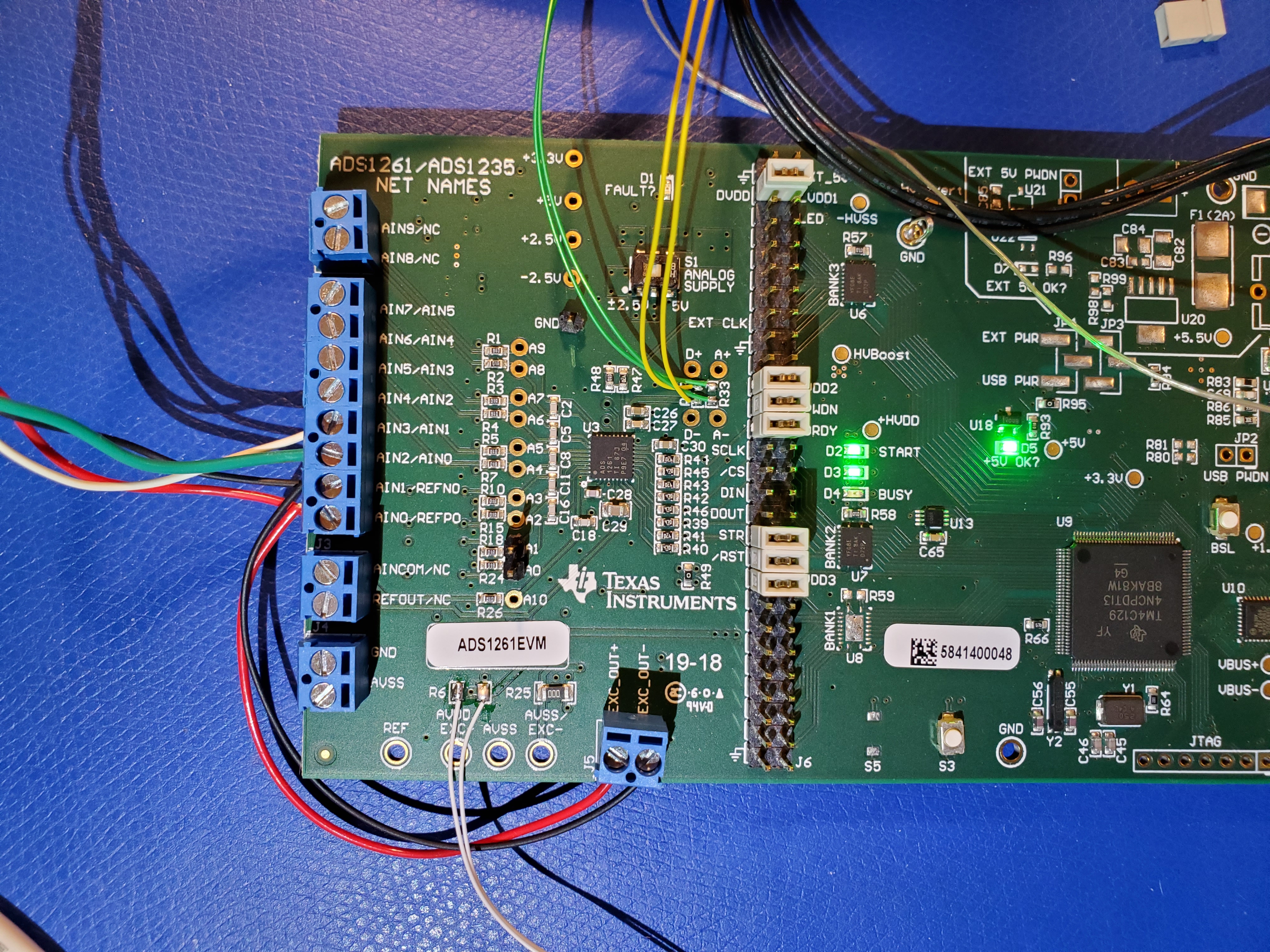
    Can you explain how you have the bridge and excitation signals connected, as well as their voltage levels? Also, an accompanying picture might help so I can see what is connected and where.

    In general, the SINC filter does require time to settle, typically related to the sinc filter order e.g. sinc 3 takes 3x conversions to provide settled data. The conversion latency is described in section 9.4.1.3 and quantified in Table 8 in the ADS1261 datasheet. But I would not expect it to take 25-30 conversions to settle. This sounds more like analog settling, which is why it might help to see how everything is wired and how the EVM is configured. Also your register settings would be helpful

    -Bryan

  • I'm using the onboard "AC Excitation" circuit as is.  EXC_OUT+/- are connected to REFP0/REFN0 respectively as well as the +/- excitation of the load cell bridge.  Bridge +/- outputs are connected to AIN0/AIN1.

    Note R6 has been removed so I could measure current, but there's a jumper across it in this setup.  I can demonstrate the issue using the TI Delta-Sigma evaluation software.  Run this script to configure the ADC1261:

    <?xml version="1.0" encoding="utf-8"?>
    <script>
      <name>Enable bridge - external reference w/ AC excitation 60 SPS Sinc3</name>
      <description />
      <command_list>
        <command>
          <command_string>RESET</command_string>
          <description>Reset device</description>
        </command>
        <command>
          <command_string>WREG 02 32</command_string>
          <description>SINC3, 60 SPS</description>
        </command>
        <command>
          <command_string>WREG 03 61</command_string>
          <description>Enable 4-wire AC excitation</description>
        </command>
        <command>
          <command_string>WREG 04 C0</command_string>
          <description>Enable GPIO Outputs on AIN4/5</description>
        </command>
        <command>
          <command_string>WREG 05 6C</command_string>
          <description>Enable STATUS/CRC bytes</description>
        </command>
        <command>
          <command_string>WREG 06 0A</command_string>
          <description>External AIN0/1 reference selected</description>
        </command>
        <command>
          <command_string>WREG 10 07</command_string>
          <description>PGA enabled, gain of 128 V/V</description>
        </command>
        <command>
          <command_string>WREG 11 34</command_string>
          <description>Select AIN2/3 as analog inputs</description>
        </command>
        <command>
          <command_string>DELAY 2000</command_string>
          <description>Delay for settling...</description>
        </command>
        <command>
          <command_string>SYOCAL </command_string>
          <description>Run system offset calibration</description>
        </command>
        <command>
          <command_string>DELAY 10</command_string>
          <description>Delay for calibration</description>
        </command>
        <command>
          <command_string>CLEAR</command_string>
          <description>Clear STATUS register</description>
        </command>
        <command>
          <command_string>REGMAP</command_string>
          <description>Readback register settings</description>
        </command>
        <command>
          <command_string>STATUS</command_string>
          <description>Check for faults</description>
        </command>
        <command>
          <command_string>DELAY 10</command_string>
          <description>Delay for settling</description>
        </command>
        <command>
          <command_string>COLLECT 300</command_string>
          <description>Collect 300 points of data</description>
        </command>
      </command_list>
    </script>

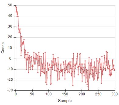
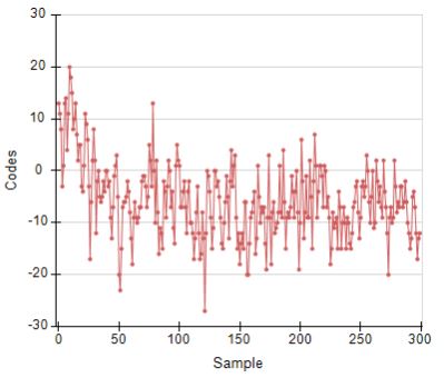
    Open the analysis engine window and you should see good data.  Go to the "device" tab in the ADC eval software and manually set MODE3 bit 7 (PWDN) to "software power down" and write the register to put the ADS1261 into power-down mode.  Then go back to the analysis engine window and click "collect data" (300 points will be sufficient); this appears to bring the ADS1261 out of power-down mode before taking data.  When it's done you should see something like this:

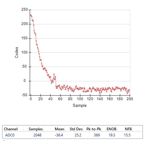
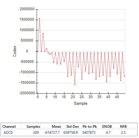
    I've also seen other weird outcomes like these:

    FYI the load cell bridge is constructed of four Galoce GML624's connected as a bridge using a SparkFun BOB-13878 "combinator" board.  The four "combinated" bridge wires are connected to the ADS1261EVM.

  • Hi Brian,

    Can you check a known test voltage and see if you can get the appropriate response out? For example, apply a 1V input signal from a precision source and read this voltage back. This at least confirms that the ADC / EVM / code is operating properly.

    Then I would try hooking up the bridge without the AC excitation and making sure you can take a valid measurement, as well as that you do not see the weird behavior you have shown here.

    I would then check to see if the voltage is swapping appropriately from the EXC pins. The last two plots you show where there are wild swings from one input to the next suggest to me that the supply voltages to the bridge are not being applied correctly.

    Let me know what you discover.

    -Bryan

  • I'm going to say ignore the last two plots above.  It appears that doing what I suggested (setting MODE3 PWDN bit true then clicking "collect data" in the analysis engine window) sometimes results in MODE3 getting set to zero, which disables the AIN4/5 outputs that are used on the EVM to do the AC bridge drive.  This appears to be an artifact of the eval software sequence I was trying to use to demonstrate the problem for you.  Forget about that.

    So instead, use the configuration script I posted above in the ADC eval software, then use this script to take the ADC into and out of power-down and acquire data:

    <?xml version="1.0" encoding="utf-8"?>
    <script>
      <name>Powerdown test</name>
      <description>&lt;description&gt;</description>
      <command_list>
        <command>
          <command_string>HOLDPWDN 0</command_string>
          <description>Force into power down</description>
        </command>
        <command>
          <command_string>DELAY 1000</command_string>
          <description>Delay 1 second</description>
        </command>
        <command>
          <command_string>HOLDPWDN 1</command_string>
          <description>Take ADC out of power down</description>
        </command>
        <command>
          <command_string>DELAY 0</command_string>
          <description>Vary the amount of this delay to see the impact on wake-up data</description>
        </command>
        <command>
          <command_string>COLLECT 300</command_string>
          <description>Collect 300 data points</description>
        </command>
      </command_list>
    </script>

    There's a "DELAY 0" in the script immediately after "HOLDPWDN 1" that allows you to vary the delay time after power-up before starting data collection.  With 0ms delay, I get this:

    With 1 second delay after taking PWDN high ("DELAY 1000"), I get this:

    With 2 seconds delay after taking PWDN high ("DELAY 2000") I get this (just about good):

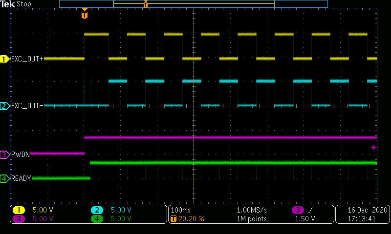
    It appears that the EXC_OUT+/- on the EVM that I'm using to drive the bridge are coming up right away, certainly not taking 2 seconds or more to get going:

    I must say that if I don't try to power down/up the ADC (or after 2 seconds have elapsed after power up), the data I'm getting looks very good.  I can place various weights on the load cell platform and the data values I get are very close to what I expect (especially since I'm not calibrating yet).

    I'll also add that this only appears when using AC excitation (4-wire AC excitation, as needs to be used with the EVM).

  • Thanks for the additional info Brian.

    Can you confirm the following: this issue only occurs after power-up / coming out of PWDN mode AND as long as AC excitation mode is being used?

    In other words, if you just came out of PWDN without AC excitation, your data is immediately valid? Or if you had AC excitation mode turned on but it had been >2ms your data is also valid? It is just both events combined that are causing the issue?

    Clarifying this will help me investigate further. Thanks!

    -Bryan

  • Yes.  If I set to either "normal" or "chop" mode in the eval software I do not see this initial data error, only when using 4-wire AC excitation (the EVM isn't set up to use 2-wire).  And the problem appears the same whether using the PWDN pin or the software (register) setting to enter/exit power-down.

    And it's 2 *seconds* delay for things to approach normal, not 2 ms.  2ms we could live with.

    - BR

  • Thanks Brian,

    I am trying to replicate the issue on my end, please give me 1-2 days to get back to you.

    If you try anything else in the meantime, please share your results.

    -Bryan

  • Hi Brian,

    I tried replicating your setup using my ADS1261EVM. Unfortunately I do not have a bridge to test, so it will not be identical to your results. But I was able to run your configuration and powerdown scripts. As you can see from the results shown below where DELAY = 0ms, I did not get the same drifting data that you did. I ran this test multiple times and did not see any meaningful difference.

    Is there any way the sensor could be loading the input to cause this slight deviation in codes? Have you modified the board in any other way other than what is shown in the images you have already sent?

    Also, it looks like in your script you are performing the system offset calibration (SYOCAL), which requires you to manually short the inputs to the ADC (or more likely the terminal blocks) to remove system offset. You probably don't need to do this since you are running the AC excitation, which is designed to remove the system offset continually. I don't think this is the source of the issue you are describing, but something to consider.

    -Bryan