


Hi Morita-san,
My customer wants to know about the timing generator.
Under the conditions of INCLK: 15MHz, SH_R: External SH_R input,
As shown in the figure below, they would like to assign the outputs of AFE pins CLK1, CLK2, and CLK4 to PIX1, MODE, and LAMPR to output a pulse signal.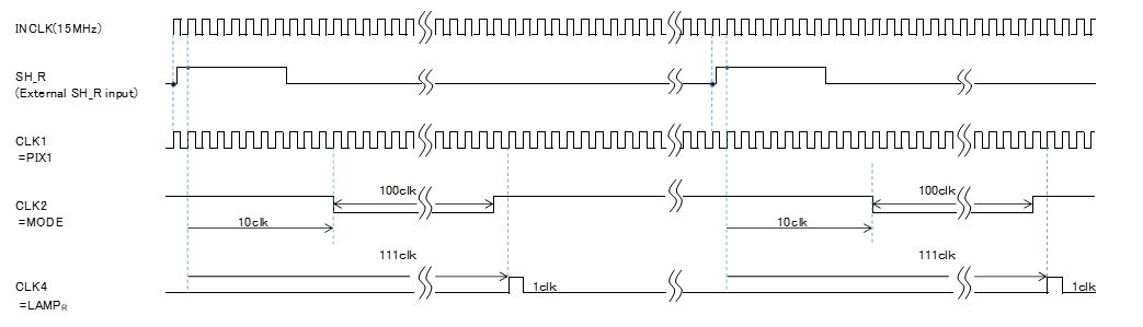
The timing shown in this figure will be set in the following registers.
Could you tell me if this register setting is correct or if there is another good register setting?
And then, please tell me what to enter for the "X" part?
・Page[0]、Address[0 0000]、Main Configuration 0[1111 0001]
・Page[0]、Address[0 0001]、Main Configuration 1[0010 0100]
・Page[2]、Address[0 0000]、SH Mode[0000 0000]
・Page[2]、Address[0 0010]、PIX1/2 Control[1001 0000]
・Page[2]、Address[0 0110]、Line Clamp Enable[0000 0000]
・Page[3]、Address[0 0000]、Output Mapping CLK1/CLK2[0001 1110]
・Page[3]、Address[0 0001]、Output Mapping CLK3/CLK4[0000 1001]
・Page[3]、Address[0 0101]、Illumination Mode[0000 0000]
・Page[3]、Address[0 0110]、Line 1 Lamp Selection[0001 0000]
・Page[3]、Address[0 0110]、LAMPR On MSB[0000 XXXX]
・Page[3]、Address[0 0110]、LAMPR On LSB[XXXX XXXX]
・Page[3]、Address[0 0110]、LAMPR Off MSB[XXXX XXXX]
・Page[3]、Address[0 0110]、LAMPR Off LSB[XXXX XXXX]
・Page[4]、Address[0 0000]、Mode On MSB[0000 XXXX]
・Page[4]、Address[0 0001]、Mode On LSB[XXXX XXXX]
・Page[4]、Address[0 0010]、Mode Off MSB[XXXX XXXX]
・Page[4]、Address[0 0011]、Mode Off LSB[XXXX XXXX]
◆Question in Japanese
Question in JAPANESE.xlsx
Sincerely.
Kengo.
