This thread has been locked.

If you have a related question, please click the "Ask a related question" button in the top right corner. The newly created question will be automatically linked to this question.

ADS131A04EVM: Using external power supply with the EVM board

Part Number: ADS131A04EVM
Other Parts Discussed in Thread: ADS131A04

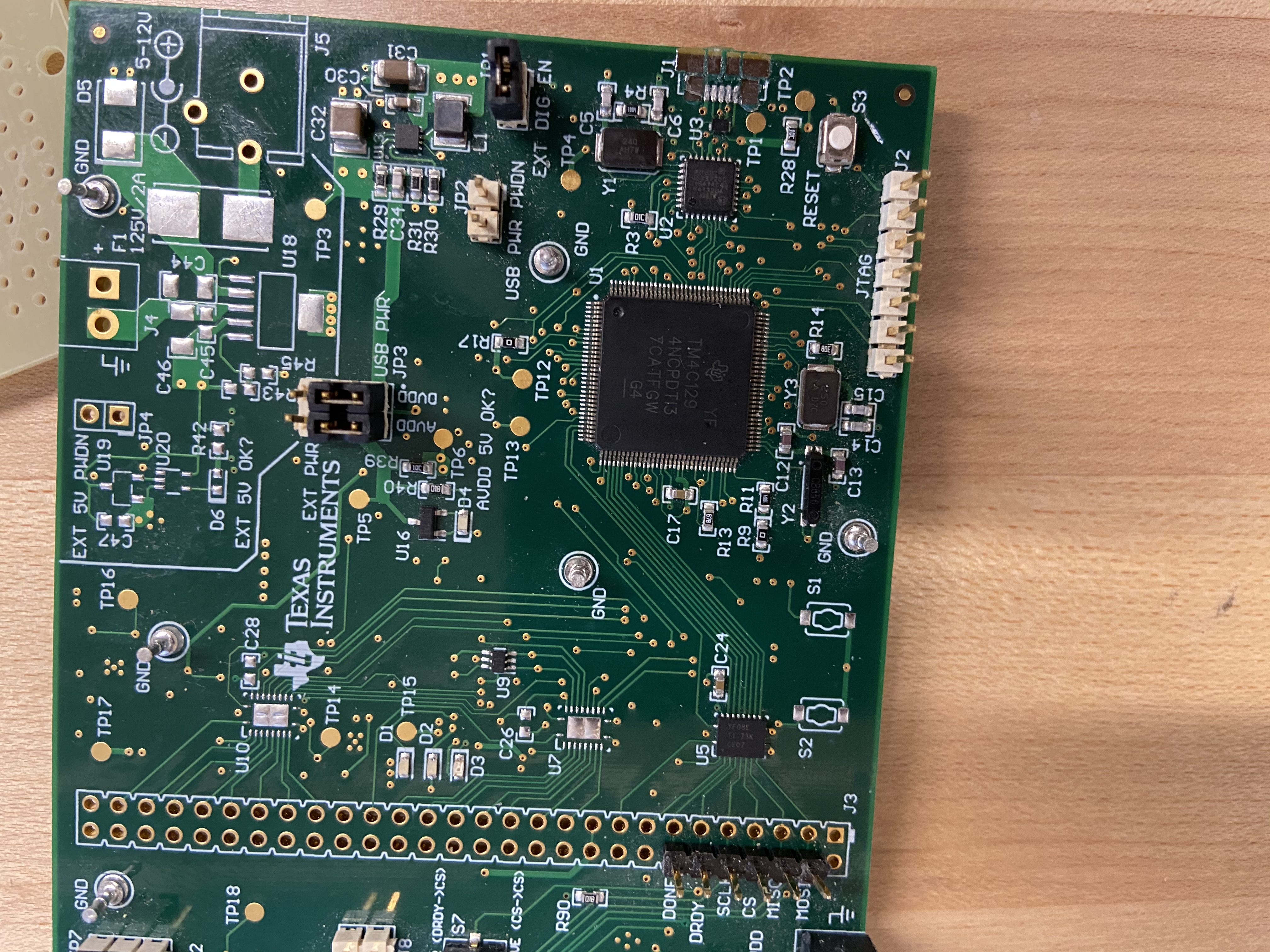
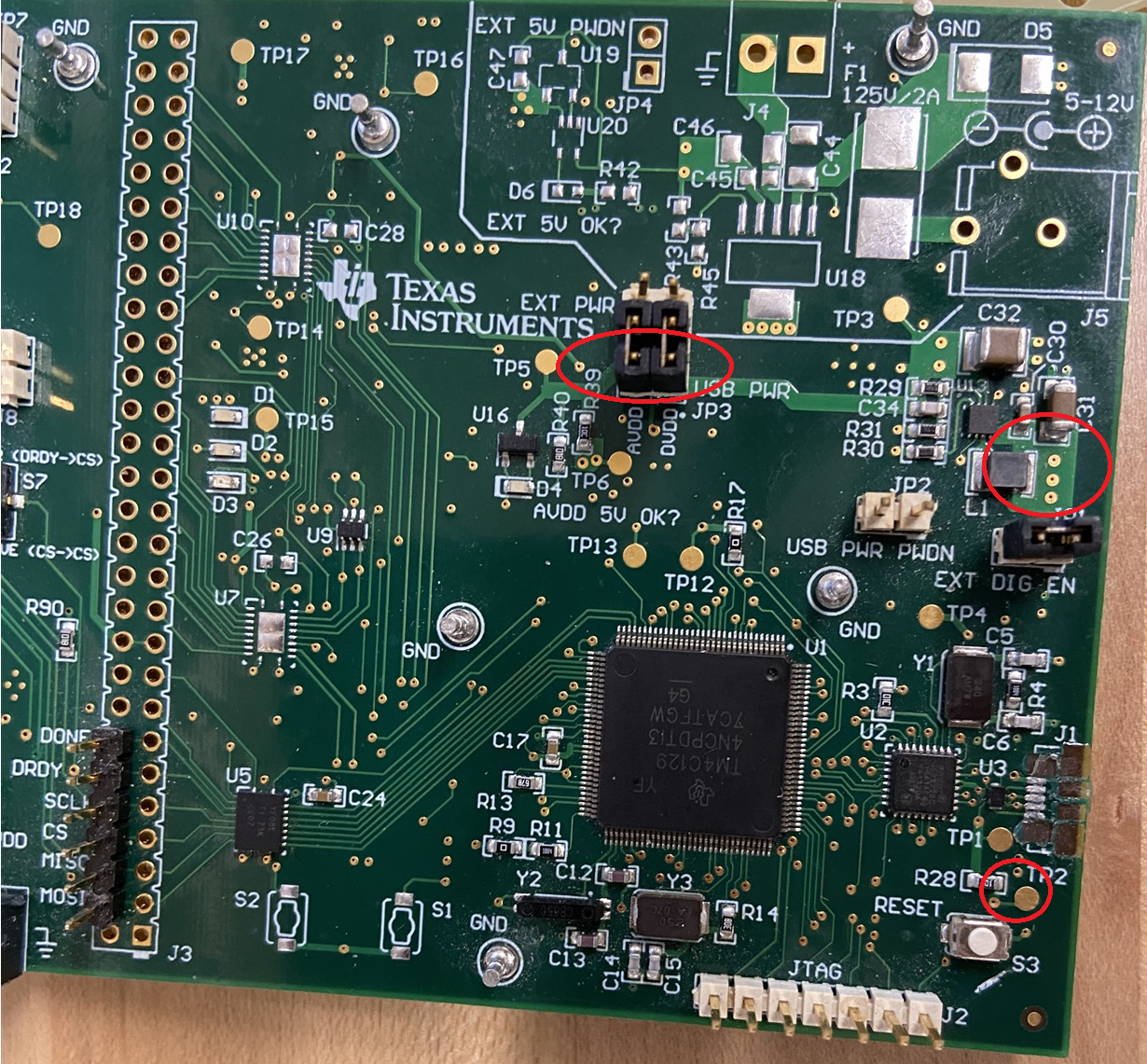
Hello everyone compliments of the season , I have been hit with a rather unfortunate turn of event. the USB connector of my evm board broke out (as shown in the picture below) i still actively use this for evaluating the ADS131a04 but the good news is i use my MCU signals from the header so the usb only serves as the power supply, I am basically posting to ask how i can use the external power supply ports provided through F1 and J5 , in a nutshell which components need to be populated or not and also what will be header positions do I leave as it was? 

Thanks for your time, Charles

  • Hi Charles,

    Happy holidays! Sorry to hear about the broken connector...

    I don't think the J4 (close to F1) or J5 connectors will be of much use to you unless you were to populate U18 and the supporting components. See https://www.ti.com/lit/ug/sbau259a/sbau259a.pdf#page=27 for a complete schematic.

    However, you could solder a wire to any of the following locations and supply it with 5V:

    The JP3 header might be the easiest to access without soldering, but you'd need to supply 5V to both of the bottom pins (labelled AVDD and DVDD).

    If that is too much of a hassle and you'd prefer to get a replacement board, let me know I can I also help get a new EVM out to you.