This thread has been locked.

If you have a related question, please click the "Ask a related question" button in the top right corner. The newly created question will be automatically linked to this question.

ADS122C04EVM: TO-CAN Analog thermopile measurement by using ADS122C04EVM

Part Number: ADS122C04EVM
Other Parts Discussed in Thread: ADS122C04, ADS1219

Hi Sir,

I have same questions need to help.

Our product is the analog thermopile (TO-CAN46 type, 4 pins).

4 pins => TS+, TS- (thermistor), TP+, TP-(thermopile).

The thermopile differential output voltage is about 2mV and thermistor resistance is 100kohm (when temperature object = 50C, temperature ambient = 25C).

How can I use the ADS122C04EVM to measure the thermopile differential output voltage and thermistor resistance?


(a)   thermopile differential output voltage is about 2mV

AINP=AIN0=TP+, AINN=AIN1=TP-, and I connected AIN1 to 2.048 voltage from external power supply.

VREF setting = internal 2.048V reference

Calculation => V(mv) = ADC code * VREF / 2^23 / Gain * 1000
For these setting and processes , that’s right?


(b)   Thermistor resistance is 100kohm

I reference to document section 5-1-1 (2 wire RTD measurement) of “SBAU297 – ADS1X2C04 Evaluation Module ‘’.

And follow Scripts 2-wire RTD setting of Delta-sigma ADC Evaluation software.

Calculation => R(RTD) = (2*R77*ADC code / PGA) / (2^24-1).

But ADC code measurement result is very big. Always is 8388607.

Could you give me some advice about thermistor resistance?


(c)    ADS122C04 spec

ADS122C04 spec => VREF = differential reference input voltage = 2.5V

And EVM board JP17- VREF is supplied by 2.5v onboard reference (U24)

ADS122C04 internal VREF 2.048V reference.

What’s difference about 2.048 and 2.5v and when to use ?

  • Hi Mei Wing,

    thanks a lot for your interest in our ADS122C04 for your thermopile measurement.

    (a) Your configuration and calculations for the thermopile measurement look correct to me.
    Just note that the ADC provides conversion data in twos-complement output format.

    (b) The thermistor measurement would unfortunately not work with this setup. You would have to make the 4.7kOhm resistor between the REFP and REFN inputs larger than the maximum resistance of the thermistor that can occur in your application. Could you let me know what the maximum thermistor value will be?
    You will also have to set the IDAC current to 10uA and the PGA gain = 1.
    Your equation looks correct though.
    Thermistor measurements are often times implemented using a resistor divider measurement instead of using a constant excitation current. In the application section of the ADS1219 datasheet I explain how this could be implemented.

    (c) An external reference would usually only be required if you need a voltage reference with lower drift over temperature or lower noise than the internal VREF of ADS122C04. 
    A larger reference voltage would be required if the input signal that you want to measure is >2.048V.

    Regards,

  • Hi Joachim,

    Thanks for the updated information.

    (b) Thermistor max ~ min value (3.25M ~6.5K ohm, when temperature at -40C ~ 100C)

    Could I connect two parts of thermopile and thermistor at the same time to measure by using EVM?

    (Example: thermopile at AIN0/AIN1, thermistor at AIN2/AIN3)

    I tested it when I connect two parts at the same time. The problem is that the two threads interfered with each other, causing a wrong final answer. In contrast, just connect thermopile at AIN0/AIN1 is fine.


    BR.

    Thank you ~

    Wade.

  • Hi Wade,

    I am afraid you will not be able to measure the thermistor using the '2-wire RTD configuration' because the maximum resistance value is too large for the 10uA excitation current. You will have to use the resistor divider implementation instead that I mentioned before.

    But you should be able to implement both measurement with the ADS122C04EVM.

    I would connect the thermopile between analog inputs AIN1 and AIN2 (pins 3 and 4 on J6) as is shown for the thermocouple measurement in the users guide. You can connect the external 2.048V to either AIN1 or AIN2 to bias the thermopile.

    You could then connect the thermistor between AIN0 and AIN3 (pins 2 and 5 on J6).
    You then need to short the following jumper pins:
    - pins 2-3 on JP6 to use AVDD as excitation for the resistor divider
    - pins 1-2 on JP9 to connect AIN0 to the thermistor
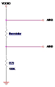
    - pins 2-3 on JP14 so that R79 and the thermistor form a resistor divider

    You should replace R79 with a 100kOhm precision resistor. You could replace R68 and R75 with 0Ohm resistors, but that is not necessary for an initial evaluation.
    You need to bypass the PGA and set the gain to 1 for this measurement.

    Let me know if this works and if you need help figuring out how to calculate the thermistor value based on this measurement.

    Regards,

  • Hi Joachim,


    Happy New Year ~

    Thank you for the quick reply.

    (a)     Thermopile measurement

    I follow your suggestion processes and results looks like OK but some questions need to clarify.

    1. Would I need to setting to thermocouple behavior include thermocouple measurement scripts, jumper J12 and J13, gain of 8 with PGA enable?
    2. These setting right? AIN1 = TP+, AIN2 = TP- and connect the external 2.048V, Gain =1, PGA enable, DR =20SPS, Normal mode, Continuous conversion mode, Internal 2.048V reference, IDACS off and IDAC1/2 disable.
    3. Based on thermopile measurement result is low voltage swing (mV level), How can I to setting DR and Gain (Gain =1 and DR = 20SPS)? Are Smaller gain and DR are better?


    (b)     Thermistor measurement

    1. I follow your suggestion and results looks like OK as in below figure for resistor divider.

    2. VDDIO=3V3, and AIN3/AIN0 read ADC code = 6333672

    3. Calculation => V(mv) = ADC code * VREF / 2^23 / Gain * 1000

               1.547V = 6333672 * 2.048 / 2^23 / 1 *1000

    (4. VDDIO * (thermistor / (100k+ thermistor) = 1.547V

         Thermistor = 88.2Kohm

    (c ) Could I connect both of thermopile and thermistor at the same time to measure by using EVM? (thermopile: AIN1 = TP+, AIN2 = TP-, thermistor: AIN3 = TS+, AIN0 = TS-)

    As I previously talked. I tested it when I connect both at the same time. The problem is that the two threads interfered with each other, causing a wrong result of thermopile. In contrast, just connect thermopile is fine.

    1. Connect both at same time

    Thermopile = 2.03m V

    Thermistor = 88.2k


    1. Connect thermopile only or thermistor only

    Thermopile = 2.35m V

    Thermistor = 88.2k

    2.35mv was closer than right answer. What is your opinion?

  • Hi Wade,

    Happy New Year to you as well!

    (a) Thermopile measurement

    • If you connect an external 2.048V bias voltage to either AIN1 or AIN2 then you would not short jumpers JP12 and JP13.
    • Except for the PGA gain setting your configuration looks good. The gain setting will depend on the maximum output signal of the thermopile.
      If the maximum differential voltage across the thermopile is only 2mV then you should use a gain of 128.
      (The maximum input signal multiplied by the PGA gain needs to be smaller than the VREF voltage of 2.048V.)
    • The lowest data rate and highest possible gain will provide the best noise performance for the thermopile measurement.

    (b) Thermistor measurement

    • Your calculations look correct. I am glad this worked out.
    • I don't see why you should not be able to connect both the thermopile and the thermistor to the ADS122C04EVM at the same time.
    • However in order to avoid any interference on the board you could remove capacitors C76 and C77.
    • Maybe the real problem is that when the thermistor is excited that it causes self-heating in the device which causes the thermopile to read a higher temperature. Maybe check with the thermopile vendor how much current is allowed to run through the thermistor without degrading the thermopile measurement accuracy.

    Regards,

  • Hi Joachim,

    Thanks for the updated information.

    As like our product application to measure the voltage and resistance by using ADS122C04.

    For now I will make the sensor circuit and application.

    How can I design the resistor and capacitor of input site as RF1, RF2, CCM2, CCM1 and CDIF (ADS122C04 datasheet, page 51, figure71)?

    Thanks~

    Wade

  • Hi Wade,

    section '9.2.1.2 Detailed Design Procedure' in the ADS122C04 explains how the R and C values could be chosen. The values given in this section are probably a good starting point for your design. The values are in general not very critical for a design that measures DC signals.

    My colleague Bryan wrote an FAQ providing some guidelines of how to choose the filter values as well:

    For the thermistor measurement a capacitor (maybe 100nF) between the analog inputs should suffice. There should be no need for additional series filter resistors.

    Regards,

  • Hi Wade,

    if you don't have any more question at this point I will mark this thread as closed.

    Regards,