


Hi,
I'm using the ADS1118 for my Master Thesis with Arduino Uno. When I tested the SPI interface, the ADC gave back 0V when asked for theSignal on AIN3 to ground and 0°C when asked for the temperature. After further investigations I made the observations described below. Would be very happy about support, since I'm out of ideas...
Supply Voltage: 5V
Input pins not connected for the test, except AIN3, which is connected to supply
Observations:
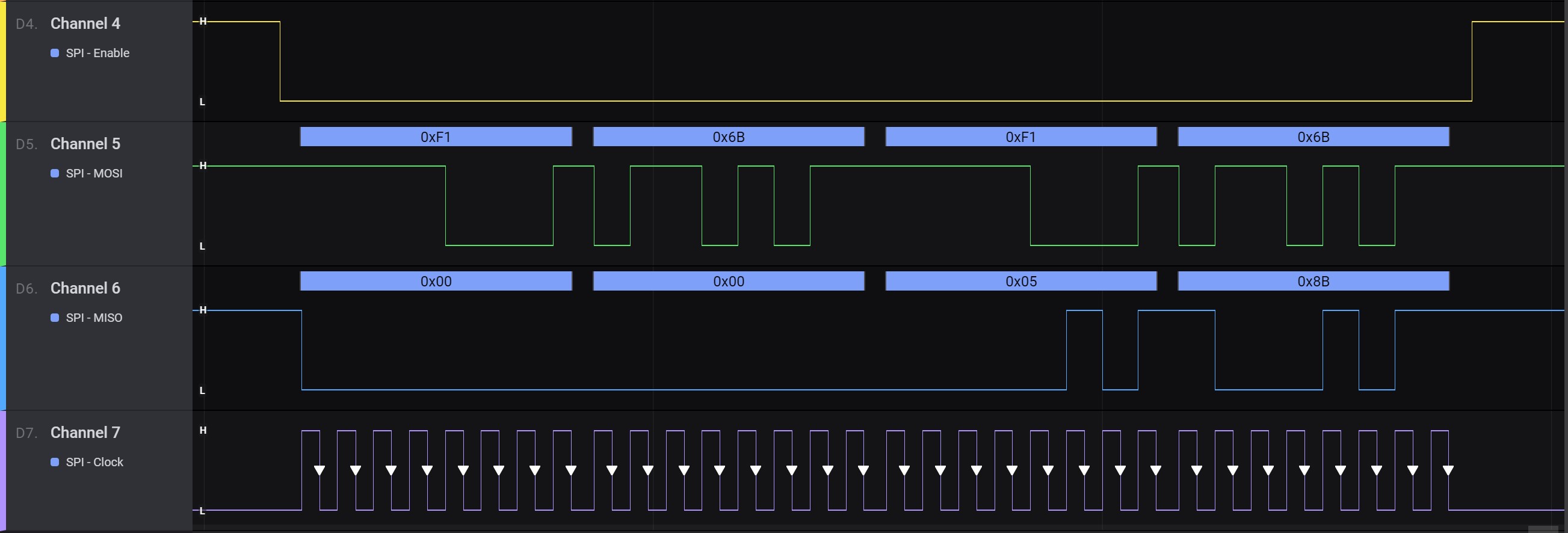
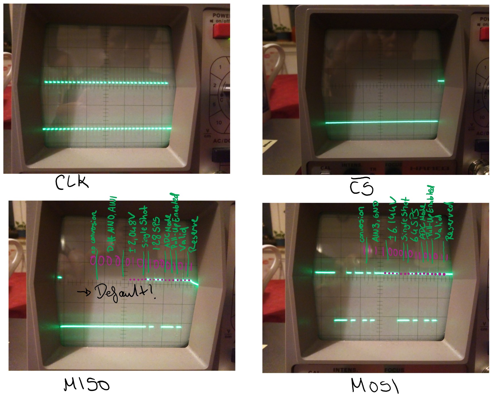
- The Arduino sends the wanted Config Register on the MOSI-wire. The signal was checked both with Logic Analyser and scope and also bit for bit compared to the data sheet. With the scope I also checked the signal on the ADC pin itself, so I am sure that the signal actually reaches the ADS1118 and there are no problems with the wiring.
- The MISO-Pin sends the value "0" as well as the current register used by the ADC. You can see that it is the default config as described in the data sheet, which for me means that the chip is working, but for some reason not updating its config register. Unfortunately, in this mode I can't check either, if the conversion itself would work (no point there anyways if the communication doesn't work, just, you know, straws...)
- Soldering mistakes are highly unlikely, I checked all the connections and they're just as they should be. I also ruled out that the chip was dmaged during soldering, for once the process itself was very quick and also I'd expect the chip to not work at all in this case.
- The clock polarity and phase setup were verified both in the code and via measurement with the scope and logic analyser.
Logic Analyser Output:
Scope:
If you need any more info, please tell me and I'll hopefully be able to provide it.
Thanks,
Nina


