This thread has been locked.

If you have a related question, please click the "Ask a related question" button in the top right corner. The newly created question will be automatically linked to this question.

DAC80501: SPI

Part Number: DAC80501
Other Parts Discussed in Thread: ADS8678

Hello everyone
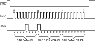
I want to create the code for the DAC80501 but it is not clear to me the data package I have to send.
I seem to have understood that the data packet is 24bit total but I still can't get the information together.
The andress bytes are 8bit but then talk about command bits which are 4 and make 12.
Where do I put the other 16bit?
thanks a lot
ms

  • Massimo,


    I'll admit that the datasheet is a little confusing. It was written to show the communication for both I2C and SPI with the data and command structure.

    If you're using SPI communications, you do not use the addresses for Table 2. The section for the DACx0501 Address Byte (described in 8.5.1.2.2.1) is used for the I2C address. To communicate with the DACx0501, you use the /SYNC pin similar to a chip select pin.

    Using SPI communications, you only need the 24 bit transfer for a valid write sequence taken from Figure 58:

    After that, you use the command byte for the first 8 bits of the 24 bit transfer, as you see in Table 4:

    And then you follow that with the data bytes from Table 5 (note that B19-B16 from the command byte are shown in the table below):

    The bits from Table 4 and Table 5 total 24 bits and that aligns with the 24 bits that you see in the valid write you see in Figure 58.

    If you use I2C communication, you need to use the I2C address from the values in Table 2. Then you follow the I2C communication byte by byte. First you send the command byte, then the MSB data byte, then the LSB data byte.


    Joseph Wu

  • thanks a lot
    now I just have to figure out how to set the first 8bit.
    I think I understand that the first 4 are zero and the other 4 are options.
    Would you be kind enough to give me an example of the first byte with a 0 to 5 Volt 16bit SPI configuration?
    Thanks again
    ms

  • Massimo,


    You are correct that the first four bits then become zero. As an example, if you want to set the output DAC to half scale you would write 8000h to the DAC DATA register. To access the register, you send 08h for the command bits. For the sequence, you would send 08 80 00 for the 24-bit transfer.

    The data lines would look like this:

    For this mode of SPI, the /SYNC acts as the chip select, and data is clocked into the device on the falling edge of SCLK.


    Joseph Wu

  • Very nice
    Thank you so much now I try.
    In the datasheet, such an example with SPI written would help a lot.
    ms

  • Hi, before asking for help again I did some tests.
    I prepared the 3 bytes 0x08h 80h and 00h then I altered the last bits to read any voltage on the DAC output.
    I have no tension.
    I wondered that there are two other 3byte groups to configure the DAC.
    With the data sheet table I built this set of 9 bytes that I found on the net.
    I haven't solved anything.
    On the oscilloscope it looks correct.
    Where am I wrong?
    Thanks so much for the replies
    ms

    CS,SCL,SDIN

    1) 0x05 00 0A // Soft-ResetDelay 200ms
    2) 0x04 01 00 // RefDiv 2, Gain 1 -> 1.25V max. Output
    3) 0x08 43 21 // some DAC code, ~ 328mV

  • Massimo,


    I don't see anything wrong with the communications that you've chosen to send to the device. The commands should set the device as described. I assume that you're using the device in the default asynchronous mode?

    For your scope shots, it would be easier to see them all on a four channel scope, so you can see the /SYNC, SCLK and SDIN on the same screen and see that the signals are aligned and the timing is correct. Go to the datasheet and check the that all the timing matches that listed. Verify the SCLK frequency, and that the data is not changing on the falling edge of SCLK.

    You can also zoom in with the oscilloscope and check that all the digital lines are clean, without other glitches in the signal.

    Can you provide a schematic to the board to show all the connections to the device? I would verify that all the connections to the device are correct. Check that the digital lines are all going to the proper pins, and that they are being received at the device pin. I would also check the reference voltage, supplies, and ground are all connected from the microcontroller to the device. I would also make sure that the microcontroller device and the DAC have the same supply. If the microcontroller is running at 3.3V and the DAC is running at 5V, then the digital output high may not be high enough in voltage to be received as a high. If this is the case you may need to run the device at a lower voltage, or add in a level translator for the communication.


    Joseph Wu

  • Thanks.
    For convenience I am using a card from the mikroE easy pic 7
    And a DAC9 module from the same company connected to the mikrobus socket.
    It has bridges which are connected for SPI and 3.3Volt
    I can tell you the links are: RE0 = CS, SCLK = RC3, SDI = RC5.
    I checked them out and they look fine.
    The micro is a Pic18f45k22 powered at 5Volt.
    I send you the schematics of everything but consider that it is a development board.
    I have the 4-track oscilloscope broken as soon as I have a moment I try to fix it.
    I didn't understand if sending the 3 groups of 3 bytes is the right thing and if they should always be sent with that sequence.
    Thank you again
    msIMG_20210127_202918_resized_20210127_082957012.rar

  • I add what Imanaged to do

  • I add what Imanaged to do

  • I had the wrong graph this is what I see with the three three byte blocksTINA Diagram2.rar

  • Massimo,


    The original posts that you showed are incorrect because each set of 3 bytes should be separated by a /SYNC pulse. Taking your original plots, this is how they should look (inserted /SYNC pulses).

    However, you most recent post shows that you correctly have the each of the three bytes separated by the /SYNC pulse (although you only show two different 3 byte communications.

    So is this what you see on the oscilloscope? What you're sending looks like TINA simulations, not a real scope plot or output from a digital analyzer. Can you get a real read from a four channel channel scope or logic analyzer?

    I've gotten your schematic and I'm looking through it. There's quite a bit to look at, and it may take some time to review it.

    Joseph Wu

  • Hi Joseph
    If you prefer, I'll make you the simplified connection diagram.
    In theory, the development board should be transparent
    and the pins of the DAC80501 are connected to the pins of the Pic 18f45k22 in the following way: RE0 = CS, SCLK = RC3, SDI = RC5.
    I have industrial Tina 12 and Tina Lab2 the measure is real but I don't know how reliable it is.
    I am sending you the lines of code I wrote to test with mikroC pro if it can be useful.
    Thanks again for the help.
    ms

    /*DAC 16bit convertitore DAC80501
    Quarzo 8 Mhz    PIC 18f45k22 */
    //SPI
    sbit Chip_Select at RE0_bit;//CS selezione CHIP
    sbit Chip_Select_Direction at TRISE0_bit;
    
    void Init()  //DAC80501
    {
    
                        // Initialize variables
    
    // Init SPI
      SPI1_Init_Advanced(_SPI_MASTER_OSC_DIV64,           // Initialize PIC as master
                         _SPI_DATA_SAMPLE_MIDDLE,            // _SPI_DATA_SAMPLE_MIDDLE,
                         _SPI_CLK_IDLE_LOW,
                         _SPI_HIGH_2_LOW );
    
      Chip_Select_Direction= 0;                           // ClearBit(TRISC,0)
      Chip_Select= 1;                                     // SetBit(PORTC,0)
    }//**********************************************************************************


    void main (){
     ANSELC=0;
     Init();
    
    
    do{
     Chip_Select= 1;
    Chip_Select= 0;
    SPI1_Write(0x05);
    SPI1_Write(0x00);
    SPI1_Write(0x0A);
    Chip_Select= 1;
    
    
    Chip_Select= 0;
    SPI1_Write(0x04);
    SPI1_Write(0x01);
    SPI1_Write(0x00);
    Chip_Select= 1;
    
    Chip_Select= 0;
    SPI1_Write(0x08);
    SPI1_Write(0x43);
    SPI1_Write(0x21);
    Chip_Select= 1;


    }
    while(1);
    }

  • Massimo,

    One thing that you can check is to see if the reference voltage is working. Check the VREFIO, which should be on as default and see if the voltage is there. Then you can use the CONFIF register to power down the reference. You can use this to check to see that the device is receiving commands.


    Joseph Wu

  • Hi Joseph
    I also tried a new same card but I only see the reference voltage at 2.48Volt.
    I tried to change various configurations but it remains fixed at 2.48Volt and at the output I have 0Volt.
    Yet there must be an error in the code but I don't understand where it is.
    I made the lines of code in C as simple as I could to see if it worked but nothing.
    From the diagrams I sent you the signal seems right.
    I have checked the connections and they seem free from external loads and connected correctly.
    I do not know for now what other tests to do.
    I would like to do some projects with these ICs but they seem to disagree.
    I'll send you the code again to see if maybe I'm wrong in choosing the bits.
    I'm sorry for the inconvenience and thank you for your availability.

    /*DAC 16bit convertitore DAC80501
    Quarzo 8 Mhz PIC 18f45k22 */
    //SPI
    sbit Chip_Select at RE0_bit;//CS selezione CHIP
    sbit Chip_Select_Direction at TRISE0_bit;

    void Init() //DAC80501
    {

    // Initialize variables

    // Init SPI
    SPI1_Init_Advanced(_SPI_MASTER_OSC_DIV64, // Initialize PIC as master
    _SPI_DATA_SAMPLE_MIDDLE, // _SPI_DATA_SAMPLE_MIDDLE,
    _SPI_CLK_IDLE_LOW,
    _SPI_HIGH_2_LOW );

    Chip_Select_Direction= 0; // ClearBit(TRISC,0)
    Chip_Select= 1; // SetBit(PORTC,0)
    }//**********************************************************************************

    void main (){
    ANSELC=0;
    Init();


    do{
    Chip_Select= 1;
    Chip_Select= 0;
    SPI1_Write(0x05);
    SPI1_Write(0x00);
    SPI1_Write(0x0A);
    Chip_Select= 1;


    Chip_Select= 0;
    SPI1_Write(0x04);
    SPI1_Write(0x01);
    SPI1_Write(0x00);
    Chip_Select= 1;


    Chip_Select= 0;
    SPI1_Write(0x08);
    SPI1_Write(0x43);
    SPI1_Write(0x21);
    Chip_Select= 1;


    }
    while(1);

  • Hi Joseph
    With this sequence I can read 1 Volt at the output but the reference remains 2.48Volt.

    /*DAC 16bit convertitore DAC80501
    Quarzo 8 Mhz PIC 18f45k22 */
    //SPI
    sbit Chip_Select at RE0_bit;//CS selezione CHIP
    sbit Chip_Select_Direction at TRISE0_bit;

    void Init() //DAC80501
    {

    // Initialize variables

    // Init SPI
    SPI1_Init_Advanced(_SPI_MASTER_OSC_DIV64, // Initialize PIC as master
    _SPI_DATA_SAMPLE_MIDDLE, // _SPI_DATA_SAMPLE_MIDDLE,
    _SPI_CLK_IDLE_LOW,
    _SPI_HIGH_2_LOW );

    Chip_Select_Direction= 0; // ClearBit(TRISC,0)
    Chip_Select= 1; // SetBit(PORTC,0)
    }//**********************************************************************************

    void main (){
    ANSELC=0;
    Init();


    do{
    Chip_Select= 1;
    Chip_Select= 0;
    SPI1_Write(0x05);
    SPI1_Write(0x00);
    SPI1_Write(0x0A);
    Chip_Select= 1;


    Chip_Select= 0;
    SPI1_Write(0x03);
    SPI1_Write(0x01);
    SPI1_Write(0x00);
    Chip_Select= 1;


    Chip_Select= 0;
    SPI1_Write(0x04);
    SPI1_Write(0x01);
    SPI1_Write(0x01);
    Chip_Select= 1;


    Chip_Select= 0;
    SPI1_Write(0x07);
    SPI1_Write(0x00);
    SPI1_Write(0x01);
    Chip_Select= 1;


    Chip_Select= 0;
    SPI1_Write(0x08);
    SPI1_Write(0xff);
    SPI1_Write(0xff);
    Chip_Select= 1;


    }
    while(1);
    }

  • Hi Joseph
    By changing the power supply to 5 Volt in the converter without division and with Buffer X2 I can get 3.9Volt at the output.
    Changing Div bit and Buffer bit I get some changes but the values are strange.
    By changing the refPWDWN bit, the ref pin remains at 2.5Volt.
    I tried to add some delays but everything stays at 3.9V.
    I read in the data sheet that the chip has an alarm that sends the output to 0 if the reference voltage does not have the space to be multiplied for this I tried to power it at 5Volt but I reached 3.9VMax.
    I tried to disable this alarm with other code but nothing changes.

    This is the code I used.

    /*DAC 16bit convertitore DAC80501
    Quarzo 8 Mhz PIC 18f45k22 */
    //SPI
    sbit Chip_Select at RE0_bit;//CS selezione CHIP
    sbit Chip_Select_Direction at TRISE0_bit;

    void Init() //DAC80501
    {

    // Initialize variables

    // Init SPI
    SPI1_Init_Advanced(_SPI_MASTER_OSC_DIV64, // Initialize PIC as master
    _SPI_DATA_SAMPLE_MIDDLE, // _SPI_DATA_SAMPLE_MIDDLE,
    _SPI_CLK_IDLE_LOW,
    _SPI_HIGH_2_LOW );

    Chip_Select_Direction= 0; // ClearBit(TRISC,0)
    Chip_Select= 1; // SetBit(PORTC,0)
    }//**********************************************************************************

    void main (){
    ANSELC=0;
    Init();


    do{
    Chip_Select= 1;
    Chip_Select= 0;

    SPI1_Write(0x05);
    SPI1_Write(0x00);
    SPI1_Write(0x0A);

    Chip_Select= 1;


    Chip_Select= 0;

    SPI1_Write(0x04);
    SPI1_Write(0x00);
    SPI1_Write(0x01);

    Chip_Select= 1;


    Chip_Select= 0;

    SPI1_Write(0x08);
    SPI1_Write(0xff);
    SPI1_Write(0xff);

    Chip_Select= 1;


    }
    while(1);
    }

  • Massimo,

    If the reference is on, then the reference will always read 2.5V. If the REF-DIV bit is set to 1, the reference is divided by internally, it does not show up as 1.25V. The best way to see if the communication is doing something, is to disable the reference to see if it turns off. However, if you are able to send the device bits and the device changes outputs, then it's likely the digital is connected correctly.

    However, the output voltage at the output is still incorrect. At this point I still don't know what's wrong. Using the EVM, I can get the device to correctly to set the output voltage. I would try the original sequence but add a few things.

    Can you add some delays (several seconds between lines) to see what each new change in code changes in the output of the device? It might help to see the changes as the code runs slowly.

    For the sequence, I'd still run the same thing as you did in the beginning but add a couple of lines.

    Start with the reset: 0x05 00 0A
    Then set the REF-DIV: 0x04 01 00

    If the device is set up as I would have thought, you should see the output set to 0.625V for a midscale reset device and 2.5V for the reference. Because there isn't anything on the output (or it's wrong) I would try adding the following.

    Disable the reference and output: 0x03 01 01

    This should set both the output and reference to drop to zero.

    Then enable the reference and output: 0x03 00 00

    This should reset the output to 0.625V and the reference to 2.5V.

    Then set the output to a new value: 0x08 43 21

    The output should be set to 0.328V. If there was a problem with the REF-DIV setting where the reference voltage is too high for the supply, the output voltage would be disabled. I want to test if the DAC output comes back when it is re-enabled with the 0x03 00 00 setting.

    One thing that I wanted to point out is that the 0x07 STATUS register is just for status. It isn't a writable register. In one of the previous posts, you had tried to write to it.


    Joseph Wu

  • Hi Joseph
    I did as you told me and everything works it was just about times between pulse trains.
    I thank you for your infinite patience.
    Now I just have to find the correct time.
    I still have a question.
    Once all the configuration impulses have been sent, should they always be sent or is it enough to send 08 00 00?
    I noticed that depending on the code length of the whole program changes the formula 5000mV / 4096 for 12bit.
    This is normal?
    Thank you very much
    ms

  • Massimo,

    I'm glad that you were able to get the output working. 

    Once you have sent the configuration, you shouldn't need to always send it. The device should keep the configuration unless a software reset was sent. When you say the program changes, can you describe it better? What was the configuration setting before, and what does it change to?


    Joseph Wu

  • Ciao Joseph, la lingua non sempre aiuta.
    Voglio dire che se ad esempio ho un convertitore ADC a 12 bit per fare il calcolo della definizione corro 5000mV / 4096 = 1.2 .... mV.
    Ora sto realizzando un programma con molte routine ea seconda del numero di routine cambia il calcolo che devo impostare nel programma.
    Ad esempio, affinché il calcolo sia corretto devo fare 5000mV / 4025.
    È una cosa normale o un bug?
    Sto facendo qualcosa di sbagliato?
    Ti ringrazio come sempre per la tua disponibilità.
    SM

  • Hi Joseph the language doesn't always help.
    I mean that if for example I have a 12bit ADC converter to do the calculation of the definition I run 5000mV / 4096 = 1.2 .... mV.
    Now I am making a program with many routines and depending on the number of routines the calculation that I have to set in the program changes.
    For example, for the calculation to be correct I have to do 5000mV / 4025.
    Is this a normal thing or a bug?
    Am I doing something wrong?
    I thank you as always for your availability.
    ms

  • Massimo,

    I'm not sure what the problem is, but I can think of two things to check. First, I would measure the reference to see if it is at the proper level. Perhaps the voltage is loaded and the output voltage is less than expected. Second, I would set the output to a series of codes and see if the output is still linear over the range. Start by setting the output code to 1000, 2000, and continue the through the full range to F000 and finally FFFF. Check to see if the output is linear to these codes. Perhaps you're including a code that is too close to ground or the supply voltage. 

    Joseph Wu

  • Thanks Again Joseph
    Before closing the topic that has been resolved I wanted to ask for advice.
    Since I got along very well with you, I set my sights on the AD 8678 ADC.
    If I had Tina 12 pro it would have been nice to have the spice models or just the symbol library but I understand that they are not there.
    I should be using AD 8678 to read voltages in some 7-segment displays and would like to know if it is suitable for use in laboratory instrumentation.
    There are no C code examples for this component.
    As you will have understood, I have recently started to implement digital in my equipment and I still do not know how to choose the right component well.
    Use of 8bit Pic 18f46k20.
    If the question doesn't fit in this topic then I'll ask you in a new one.
    Thanks again.
    ms

  • Massimo,

    Are you asking about the ADS8678 ADC? I'm not to familiar with this device. If you need some guidance working with it, post back to the forum with a new thread and another apps engineer will pick it up.

    Joseph Wu