This thread has been locked.

If you have a related question, please click the "Ask a related question" button in the top right corner. The newly created question will be automatically linked to this question.

ADS7142: Not able to read data of second channel

Part Number: ADS7142
Hello,
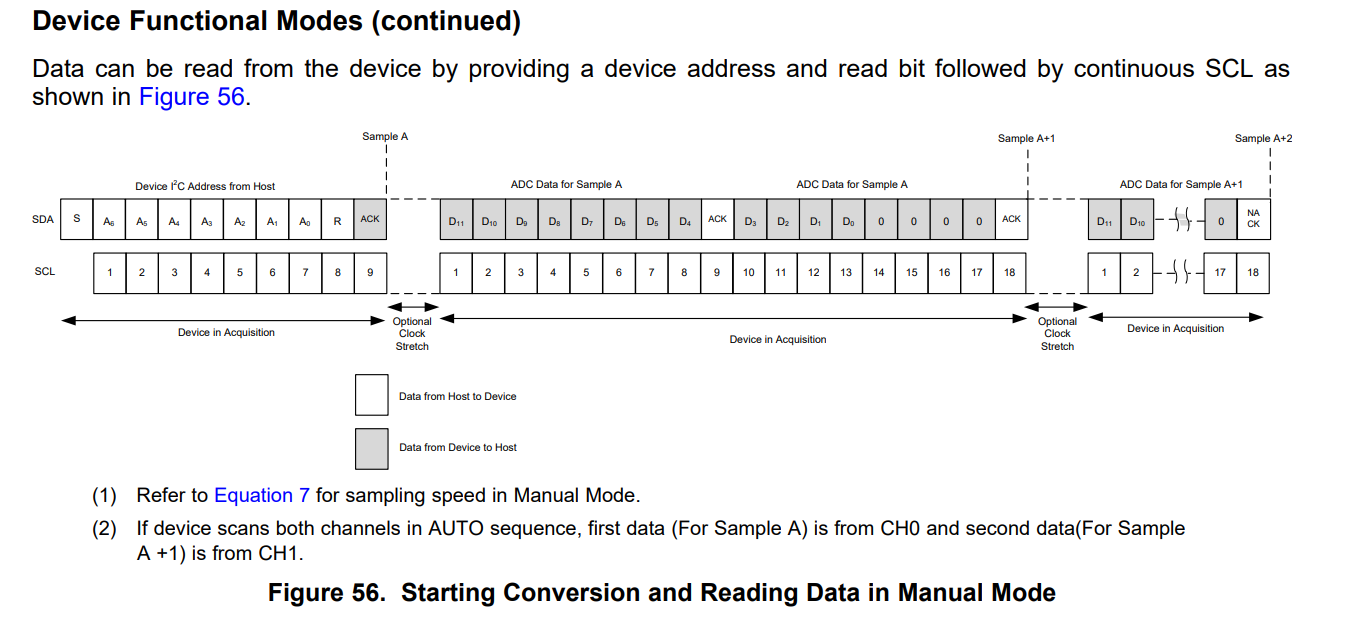
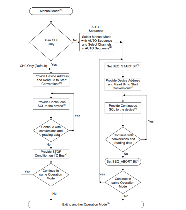
We are interfacing ADS7142Q1 with SPC 584B controller over I2C. We are configuring it to both Channels enabled in Single-Ended Configuration, Manual mode.
We are able to read CH0 data but CH1 data is not getting updated in ADS buffer. We are suspecting that configuration are not getting set.
We have seen the SDA and SCL waveforms and we verified the data is correct.
Please suggest what could be the reason and resolution.

One more query:

We have 4 ADC device connected on single I2C bus, then is it possible any one device can drive busy line high and it keeps SCL low?

Regards,
Nimesh Rana
  • Hello,

    At start up the device is by default set to Two channel, single ended, and manual mode. But the device can only sample Ch0 in this mode, this is why you cannot sample channel 1. 

    To configure to sample either CH0 or CH1 or both channels, set bits in AUTO_SEQ_CHEN register to select the channels (either of the below are viable options).

    • To select a channel in AUTO sequence, set AUTO_SEQ_CHx bit in AUTO_SEQ_CHEN register to 1.

    • Set bits in OPMODE_SEL register to 100b or 101b for Manual Mode with AUTO sequence.

    • Set bits in OPMODE_SEL register to 110b for Autonomous Modes with AUTO sequence. 

    • Set bits in OPMODE_SEL register to 111b for High Precision Mode with AUTO sequence.

    Any I2C bus needs to be addressed before it is able to control the SCL. Once an ADC is addressed, it is possible for it to hold SCL low. One reason is clock stretching, the device will hold SCL low until it is done completing the current task, and release it once it is done.

    Regards

    Cynthia

  • Thank you Cynthia for reply.

    We are writing the AUTO_SEQ_CHEN register to 0x03h to select both channels and OPMODE_SEL register to 100b for Manual AUTO sequence.
    For I2C bus addressing we have sent I2C general call with 0x04h command.

    When we read the AUTO_SEQ_CHEN or any other configuration reg we are getting only CH0 data and no config register data.

    Following are our sequences.
    1. Read single Register sequence:
    • I2c Write(slave address, 0x10, reg address)
    • I2c Read(slave address, 1)
    2. Write single Register sequence:
    • I2c Write(slave address, 0x08, reg address, reg data)
    3. ADS Init sequence for manual mode:
    • I2c Write(slave address, 0x08, 0x1f, 0x01) //abort sequence
    • I2c Write(slave address, 0x08, 0x15, 0x01) //offset calibration
    • I2c Write(slave address, 0x08, 0x24, 0x03) // input channel config reg - both Channels enabled in Single-Ended Configuration
    • I2c Write(slave address, 0x08, 0x1c, 0x04) //select operation mode as Manual
    • I2c Write(slave address, 0x08, 0x20, 0x03) //select both channels for AUTO Sequencing
    • I2c Write(slave address, 0x08, 0x28, 0x02) // Select the Data Buffer output data Configuration
    • I2c Write(slave address, 0x08, 0x1e, 0x01) // Set the SEQ_START Bit to begin the sampling sequence
    Please let us know are we missing something?
  • Nimesh,

    The general call command you are sending out (0x04) is not a real command for the ADS7142, thus this command is being ignored. 

    Instead of using the general call to configure the device, I suggest communicating with only the ADC using its address, and using the Opcodes in table 4 of the datasheet. 

    As or your sequence, it seems correct. After you set the SEQ_START bit, do you provide the device address and provide continuous SCL? The figure below shows how to sample and read the data in manual mode

  • Thank you Cynthia for reply.

    We have observed the general call with 0x04h command behavior as mentioned in datasheet as below.
    7.3.10.3 General Call With Write Software Programmable Part of Slave Address

    On receiving a general call (00h) followed by 04h, the device configures its own I2C address configured by the
    ADDR pin. During this operation, the device keeps BUSY/RDY Pin high and does not respond to other I2C
    commands except general call.
    We are able to receive CH0 data by providing continuous SCL but not CH1 data or any other register data although we configure it as per sequence in datasheet.
    We observed that whatever configurations we do they are not taking any effect.
    Please let us know if we have to do some steps before doing configurations so that device will be configured correctly.
  • Cynthia,

    I am the application engr. supporting this customer. 

    We need simple steps to read 2 channels with this device.

    Pls. help out with the steps needs to follow.

    Mitesh

  • Mitesh, 

    Good catch! you are doing the general call before any of the mentioned communication, correct?

    You are configuring he device correctly. Are you following the chart to read the data?

    After setting the SEQ-START bit, to read the data you need do you provide the device address and provide continuous SCL.

    The figure below shows how the flow of how to read the data in manual mode.

  • Thank you for your support Cynthia and Mitesh.

    The problem is solved we are able to read both channels data.

    Previously we are using i2c write function to send slave address, opcode and register address and i2c read function afterwards but was not aware the I2c driver read function was designed to write slave address and register address first and then start read operation.

    Modified it to just do read operation and used i2c driver write function to send slave address, opcode and register address before calling i2c driver read function.

    Best Regards,

    Vijayalakshmi Chavan.4