Hello everyone,
I did create a PCB breakout board for the ADS1292. I want to integrate it into a mobile system. For this I did connect the SPI interface of the ADS1292 to my Arduino Nano 33 BLE.
I tried to follow the layout guidelines from the datasheet of the ADS1292.
Now I have the PCB and want to read the ID of the ADC to confirm that everything is correct, but I cant read the Output. I only receive zeroes as a response in my IDE.
I did check with an oszilloscope the power supply. Analog supply (AVDD) is 3.36 V and digital supply (DVDD) is 3.12 V.
My OP commands are
val0 = SPI.transfer(0x06); // Reset device
val1 = SPI.transfer(0x11); // Stop Read Data Continuously mode
val2 = SPI.transfer(0x20); // Address of ID register
val3 = SPI.transfer(0x01); // Read one register
val4 = SPI.transfer(0x00); // Waiting for response
val5 = SPI.transfer(0x00); // Waiting for response
val6 = SPI.transfer(0x00); // Waiting for response
val7 = SPI.transfer(0x00); // Waiting for response
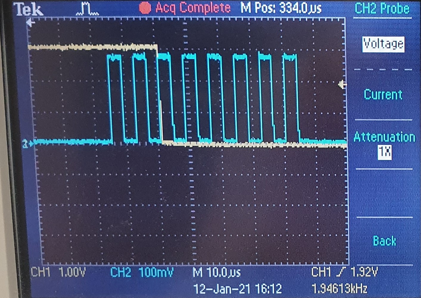
When measuring the output pin I see this strange graph. I did expect to see single bits coded as high or low in the frequence of the SCLK. (Yellow DOUT, Blue SCLK)


Any help would be appreciated to find my mistake.
Kind regards
Marco