This thread has been locked.

If you have a related question, please click the "Ask a related question" button in the top right corner. The newly created question will be automatically linked to this question.

RE: ADS125H02: CS2 is not working properly

Other Parts Discussed in Thread: ADS1261

Hi Bryan, 

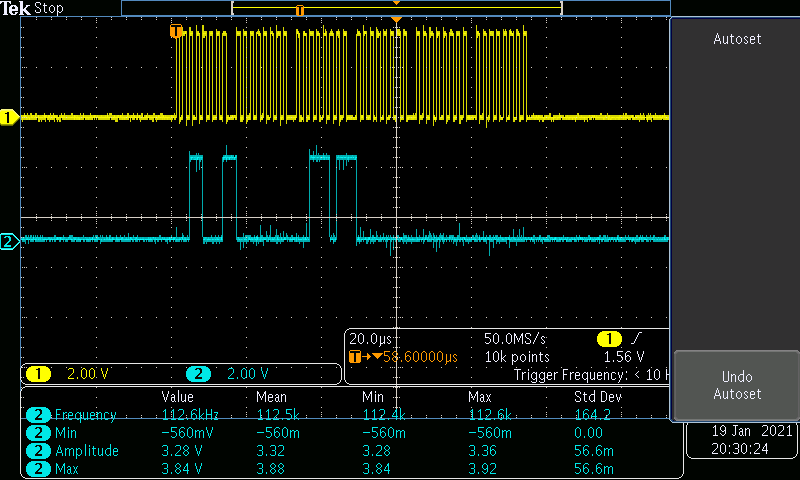
I tried to program for PGA by selecting CS2, chipselect clock and MISO are working fine but not getting the desired output

  • Hi Sasi,

    Can you explain to me what you are showing in the image you just sent? I am assuming the blue signal is SCLK and the yellow signal is DOUT, but the DOUT signal does not look clean at all and you say that it is working fine. Are you making sure that CS1 is high during the transactions with CS2, otherwise there will be contention on the SPI bus?

    -Bryan

  • Hi Bryan,

    The blue signal is SCLK and the yellow signal is DOUT. DIN, SCLK, and CS2 are working fine except DOUT, whereas when working in CS1 I am getting the desired output, I am trying to configure ADC multiplexing input

  • Hi Sasi,

    Is CS1 high during the communication period that CS2 is low?

    Can you send me a scope shot of DIN and DOUT together, as well as both CSx pins?

    -Bryan

  • Hi Bryan,

    yes CS1 is high, CS2 is low  during the communication period

    first image - yellow line CS2, blue line CS1

    second image - yellow line CS2, blue line clock

    third image - yellow line clock, blue line input

    fourth image - yellow line input, blue line output

  • Hi Sasi,

    What command are you trying to send in these images? If I look at the third image, it seems like the first 8 SCLKs correspond to 0011 0001b = 0x31 on the DIN line, which is not the beginning of a valid command on the H02. Admittedly it is hard to tell how the falling edge of SCLK corresponds to the activity on DIN since the image is so small, but I tried to blow it up. See my annotations below.

    So it would make sense that you are not getting any valid result on DOUT since the device is not receiving a valid command.

    -Bryan

  • Hi  Bryan,

    I am using the RREG (20h+rrh) command for status1 register (11h) so the first command is 31h

  • Hi Sasi,

    Indeed you are correct, I am mixing this device up with its sister device, the ADS1261, that does not have the same register map.

    Have you changed anything else between sending the RREG commands to the registers enabled by CS1 versus CS2? The communication looks valid to me: correct commands, correct CRC, etc., so it is not clear what else could be going on if you are getting the correct output for all of the commands via CS1.

    Have you tried reading back or writing to the MODE4 register to see if you get a different result?

    Can you swap the CS lines to make sure there is not an issue with the MCU GPIO pin? Since you know that CS1 is working as intended, trying swapping this GPIO output to the CS2 pin and see if that makes a difference.

    -Bryan

    **NOTE: post was resolved --> "we changed the CS2 and configured the MODE4 register  and it is working fine"