This thread has been locked.

If you have a related question, please click the "Ask a related question" button in the top right corner. The newly created question will be automatically linked to this question.

DAC8775: DAC8775 Accuracy in different current output ranges

Part Number: DAC8775

Hello,

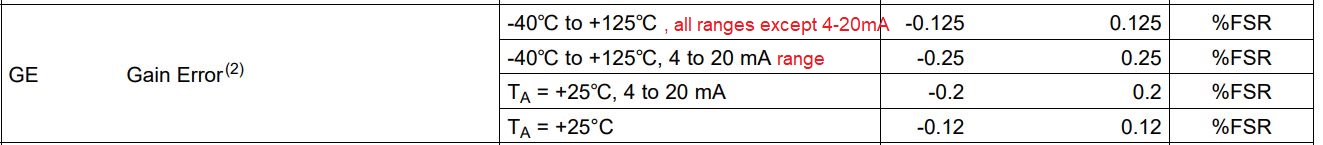
I have faced a question ragarding the accuracy of DAC8775 when set to work in different current output ranges. In the datsheet I could only find the accuracy range for 4..20mA output range.

Would you please help me figuring out how much error (TUE: Total Unadjusted Error) I should expect from the chip in 10mA / 5mA and 2.5mA output ranges ?

Do I need calbration to achive < 0.2% accuracy for mentioned output configurations ?

Thanks 

Erfan

  • Erfan,


    First, I want to direct you to the following DAC Essentials article:

    e2e.ti.com/.../dac-essentials-how-accurate-is-your-dac

    It discusses TUE and how it is calculated. In a lot of DACs the primary contributor to error is the gain error. I would note that this calculation does not consider the reference error. For whatever reference you use, you would need to include that in your calibration or the reference error becomes an additional gain error.

    With the reference error, it is likely that you would need to do some sort of calibration. What range do you intend on using? The post you wrote listed some current values, but those values look like some portion of a complete range.


    Joseph Wu

  • Hi Joseph,

    Thanks for your reply. 

    My question is about the TUE determining values in various ranges for DAC8775. In reply to your mentioned point, yes the values are part of a bigger range. In the datasheet the GE value is only mentioned for 4-20mA range.

    The Current ranges that I am intended to use are 0-20mA and +/-24mA. Can I apply the same GE values (TA = +25℃) for output current values starting from 0mA up to 4mA or 0mA to -20mA ? 

    Best Regards 
    Erfan

  • Erfan,


    Ok, I see your question. The specifications for the device are split with the different ranges. For example in the datasheet, it would have been better for us to show specifications this way:

    For the most of the IOUT ranges the TUE is the lower value. However, for the 4-20mA range, the TUE is higher. This is because of the way the IOUT is set up internally. The 4-20mA range has more error because the zero code starts with 4-20mA range starts at 4mA. This large pedestal starting point adds some additional error in implementation. That is why the 4-20mA range is specified separately.

    If you intend to use the 0-20mA and ±24mA ranges, then you would use the lower error values for the entire range.


    Joseph Wu

  • Joseph, 

    Thanks for the clarification. 

    On top of the electrical characteristics table it is mentioned that an external reference is used " REFIN= +5 V external “. Based on the reference design (EVM),  a REF5050IDGKT is used for reference with 0.05% error. 

    Does the Gain Error value include the 0.05% reference error? Or, is the reference error included in given information in the datasheet?

    Best Regards 
    Erfan 

  • Erfan,

    The gain error does not include the error from the reference. The reference error is separated from the gain error in for the electrical characteristics table. This is a standard method for calculation. 

    Joseph Wu

  • Hi Joseph,

    Thanks for the support. 

    BR
    Erfan