This thread has been locked.

If you have a related question, please click the "Ask a related question" button in the top right corner. The newly created question will be automatically linked to this question.

ADS8684: ADC reading value keep changes on every scan

Part Number: ADS8684

Hello, 

 I am using ADS8684 with dspic33 microcontroller its integrated with channel 0, when I scan channel 0 the ADC values keep changes even if voltage remain same. 

My code is as per below:

void adcInit()

{
  adcCmdreg(MAN_Ch_0);
}


void main()

{

uint16_t result = 0;
UINT8 MSB = 0;
UINT8 LSB = 0;

while(1)

{

adcCS_Low();
SPIPut(2,reg);
SPIPut(2,0);
MSB = SPIPut(2,0);
LSB = SPIPut(2,0);
adcCS_High();
result = ( MSB << 8) | LSB;
} }

Any Help.

Thanks

Rakesh 

  • Hi Rakesh,


    Can you please provide a few oscilloscope plots for CS, SCLK, SDO and SDI? This will allow us to verify the timing. Please place the probes right at the pins of the device.

    Also, can you please measure the voltage on the REFIO and REFCAP pin?

    If you have a schematic available, we could review as well.

    Thanks&regards,

    Dale

  • Thank You Dale, 

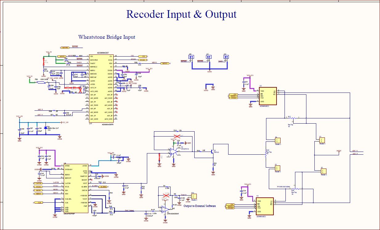
    Schematic as per below  attached. 

    REFIO PIN and REFCAP both have voltage: 4.48V 

    I don't have oscilloscope but have Logic analyzer can send data soon. 


  • Hello Dale,

    I am able to write and read the command values now.. after turning the SPI mode to 0. 

    But still there is no consistency in repeat result of ADC. 

    My voltage between PIN 16 and 17 is 1.78Volt and ADC gives results as per below: sometime its give value 0 which is strange. 

    Even I change the PIn 16 and 17 voltage to 0.7Volt, it gives me same below result.

    0x7FF1
    0x7FF6
    0x8F4C
    0x8004
    0x8002
    0x8005
    0x8037
    0x8054
    0x7FF0
    0x7FF7
    0x0000
    0x90A2
    0x8006
    0x8002
    0x8005
    0x8037
    0x8053
    0x7FF0
    0x7FF6
    0x0000
    0x8003
    0x8001
    0x8005
    0x8037
    0x8054
    0x7FF1

    My code is as per below 

    void main()
    {
      adcInit();
      while(1)
       {
          adread();
       }
    }
    
    
    uint16_t  adcCmdreg(UINT8 reg)
    {
        uint16_t  result = 0;
        UINT8 MSB = 0;
        UINT8 LSB = 0;
        
        adcCS_Low();
        SPIPut(2,reg);
        SPIPut(2,0);
        MSB = SPIPut(2,0);
        LSB = SPIPut(2,0);
        adcCS_High();
        
        result = ( MSB << 8) | LSB;
    }
    uint16_t adcReadReg(UINT8 reg)
    {
        uint16_t  result = 0;
        UINT8 MSB = 0;
        UINT8 LSB = 0;
        
        adcCS_Low();
        SPIPut(2,((reg << 1) | 0x00));
        SPIPut(2,0);
        MSB = SPIPut(2,0);
        LSB = SPIPut(2,0);
        adcCS_High();
       
        result = MSB<<8;
        result |= LSB;
        
        return result;
    }
    
    void adcInit()
    {
        adcCmdreg(MAN_Ch_0);
        __delay32(10000);
        adcCmdreg(AUTO_RST);
        __delay32(10000);
    }
    
    void adread(void)
    {
        UINT16 adcData;
        __delay32(10000);
        adcData = adcReadReg(NO_OP);
        __delay32(10000);
    }


  • Hi Rakesh,

    The 4.48V on the REFIO and REFCAP is incorrect, the voltage on these pins should be 4.096V, please use a precision multimeter to double check.

    It's really hard to see your schematic because it's not clear. However, a couple of errors have been found in your circuit:

    1. Daisy pin should be connected to the ground instead of VCC_5V. 

      If an application uses a stand-alone device, the DAISY pin is connected to GND. see the Figure 70 and section 8.4.1.1.5 in the datasheet.

    2. ADS8684 can only accept single-ended input signal and the AIN_xGND pin should be connected to the ground. You are connecting a differential signal to the ADC's input.

    3. Pin 1(SDI) and pin 2(/RST/PD) should be connected to DVDD (VCC_3V3) if a pull-up is expected, not VCC_5V.

    4. A solid ground plane is strongly recommended, and a single point connection between SGND and GND is not recommended.

    Best regards,

    Dale

  • Thank You  Dale, 

    I did change as per your suggestion.. I applied external voltage at AIN_0P and AIN_xGND.. when vary the voltage i did get the ADC count.. 

    ADC has to be read as per below code. rest initialization will be as per previous code 

    void adread(void)
    {
    adcData = adcCmdreg(MAN_Ch_0);
    __delay32(10000);
    adcData = adcReadReg(NO_OP);
    __delay32(10000);
    }

    Thanks for your support Dale. 

    Rakesh P