This thread has been locked.

If you have a related question, please click the "Ask a related question" button in the top right corner. The newly created question will be automatically linked to this question.

ADS1248: Schematic review for multiple 2-wire PT100 RTD measurement

Part Number: ADS1248
Other Parts Discussed in Thread: ADS124S08

Hello TI Team,

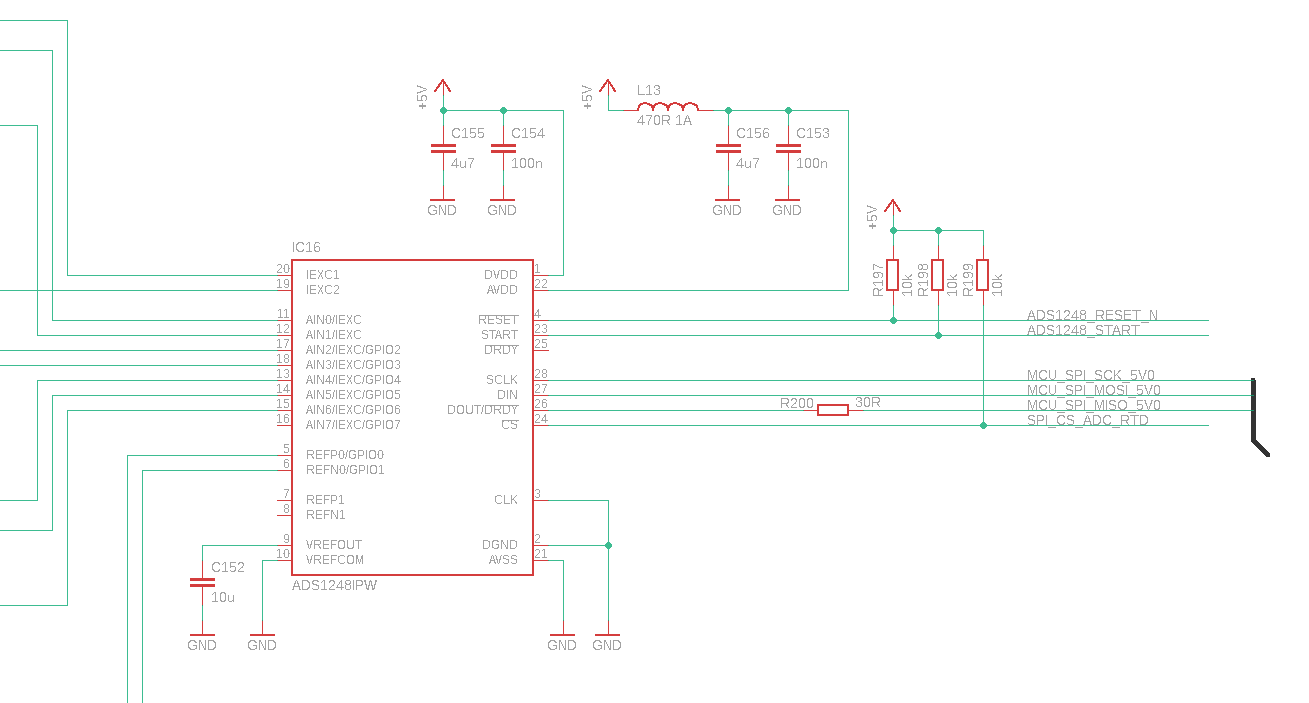
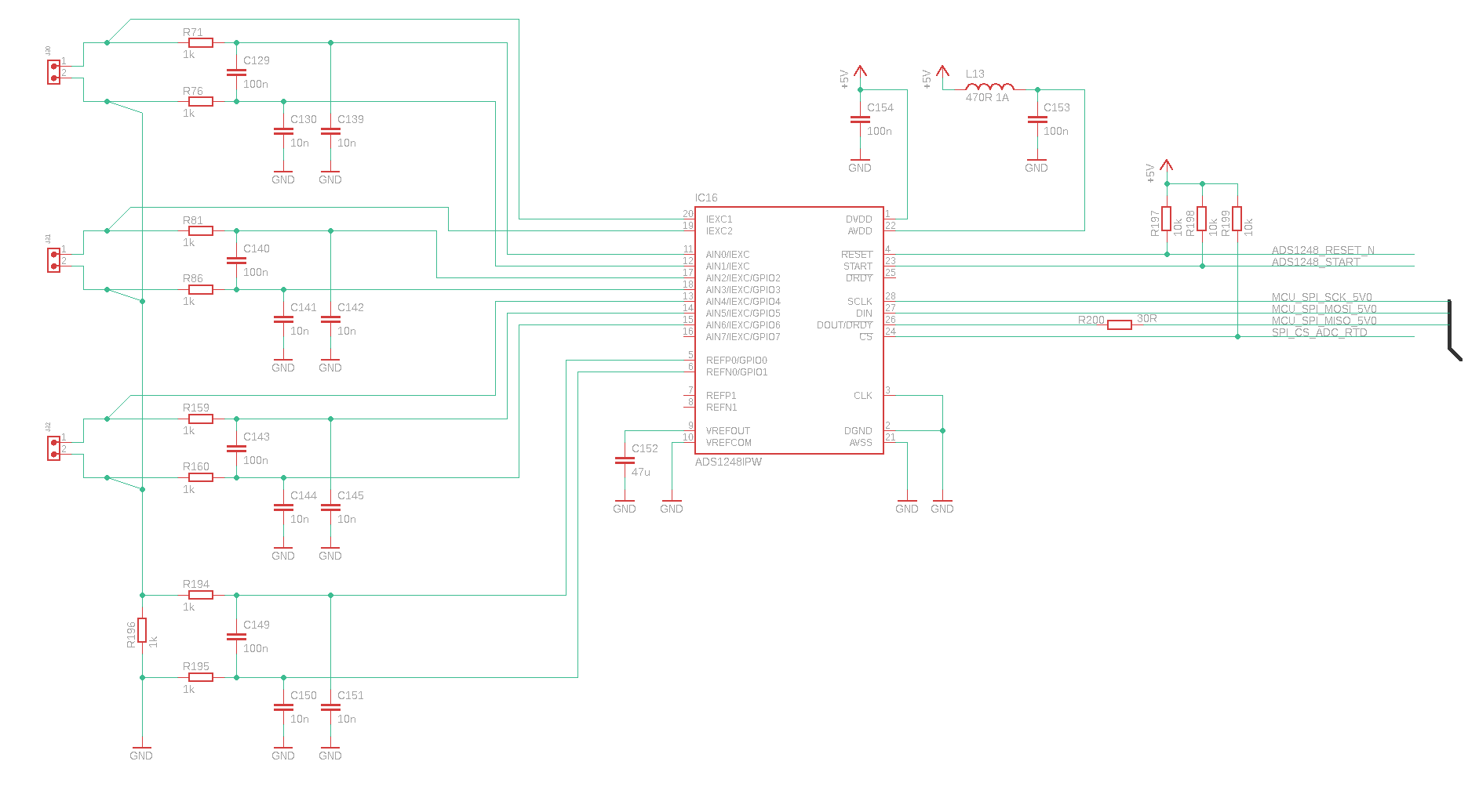
in a project we want to use two ADS1248 to measure six PT100 RTD sensors. Three sensors are measured with one ADS1248. Could you please review the implementation of the cuicuit? Basically, the circuit was implemented close to the data sheet and the basic rtd guide from TI. The excitation current is 1mA. The following schematic shows one ADS1248 with three sensors. The other one is constructed identically. The sensors are connected to the pcb with a cable length of 1..2m.

The setup of IDAC and AIN pins can vary with the layout design, but the concept is the same. I got the following questions for this schematic:

General:

Is the circuit design fundamentally correct?

For the reading of six PT100 sensors are two ADS1248 necessary. In our configuration we read 3 sensors with one ADS1248. In another post here in the forum I see an setup with 4 sensors on one ADS1248 (https://e2e.ti.com/support/data-converters/f/73/t/318269?ADS1248-SCHEMATIC-FOR-2-WIRE-PT1000-RTD. Is it more recommended to read 3 sensors with one ADS1248 or can 4 sensors be read just as easily and stable with an ADS1248? With regard to the layout, 3 sensors on an ADS1248 would make more sense for our application, since we have to use 2 ADS1248 anyway to read 6 sensors.

Power supply:

Are 100nF ceramic capacitors for AVDD and DVDD sufficient or should one more ceramic cap with 4,7...10uF added? Should an electrolytic capacitor used in front of both ADS1248?

Analog part:

Has the component dimensioning of the analog signal filter been chosen sensibly? (1kOhm, 100nF, 10nF)

Which value should be chosen for the VREF CAP (VREFOUT) in this application? Can a normal ceramic capacitor used for VREFOUT?

Digital part:

In our application we wont control the START pin with an microcontroller. Can the START pin hold high permanently? We also wont use the DRDY function. In this application, we only want to control the ADS1248 with SPI. Is this recommended? The RESET pin is controlled from microcontroller.

  • Hi Tony,

    Each RTD requires a minimum of 2 differential inputs to measure the voltage across the RTD. So if you have 6 sensors that is 12 channels. Then you also need a pair of differential reference inputs for the ratiometric reference. And finally you need at least one IDAC channel + MUX, or up to 6x IDAC channels. At a minimum then you need 13 analog inputs and 2 reference inputs for 6x two-wire RTDs. I recognize that you might be too far along in your design to switch ADCs, but you could always consider the ADS124S08 as an alternative. The ADS124S08 is the next-gen version of the ADS1248, offering 13 analog input channels and 2 reference inputs. If this is not an option for your current system, maybe consider it for future revisions or new projects.

    If you keep the ADS1248, then I would guess it makes sense to just use 3x sensors per ADC. That will help keep the layout simple and symmetric.

    Using 100nF caps should be sufficient for the supply pins. The ADS1248EVM uses 0.1uF X7R caps on both supplies, so that is a good place to start.

    The analog filtering looks correct, you have a cutoff of ~1.6kHz. The filter resistors are generally designed to limit current into the device. You can learn more about that here if you are interested: https://e2e.ti.com/support/data-converters/f/73/t/955466?tisearch=e2e-sitesearch&keymatch=faq%3Atrue

    The cap on REFOUT needs to be between 1uF and 47uF. The ADS1248EVM uses a 10uF X7R cap, so that is a good place to start.

    If you do not want to use the START pin and instead rely on commands, then hold the START pin high. This is described on pg. 37 in the ADS1248 datasheet.

    How you will you know when new data is ready if you will not use DRDY? Using the combined DOUT/DRDY pin then?

    And what will you do with CS - tie it permanently low? This is certainly possible, but it helps to have CS available in case you need to reset the SPI interface for some reason.

    -Bryan

  • Hello Bryan,

    thank you for your reply. Yes, i have to keep the ADS1248. I will change the cap on VREF to 10µF. One more question related to the ADS1248EVM: I see here 10µF caps on each supply pin. I had a look to the user guide in https://www.ti.com/tool/ADS1248EVM-PDK. I added 4,7µF caps to each supply pin. Do you recommend this? Also in adition with the ferrite bead on AVDD?

    Bryan Lizon86 said:

    How you will you know when new data is ready if you will not use DRDY? Using the combined DOUT/DRDY pin then?

    And what will you do with CS - tie it permanently low? This is certainly possible, but it helps to have CS available in case you need to reset the SPI interface for some reason.

    In our application we mux to the AIN channel, let the ADS1248 measure, doing some other stuff with the microcontroller and then we came back "later" to the ADS1248 to get the result. After that we mux to the next channel and so on. The CS signal is tied to 5V. Whenn the spi communication is going on, CS is turned low from the microcontroller.

  • Hi Tony,

    We are in the process of updating the ADS1248EVM and I was looking at that schematic, not the current version. But adding 10uF caps on the supplies is acceptable as well.

    -Bryan

  • Hello Bryan,

    thank your for your reply. One last question: Which ESD protection diode parts can you recommend to place near the connectors to protect agains esd events?

  • Hi Tony,

    TI has a new series of flat-clamp TVS diodes that you can check out. There are 12 options, depending on the clamp voltage you need as well as unidirectional vs bidirectional: https://www.ti.com/interface/circuit-protection/esd-protection-and-tvs-surge-diodes/products.html#p2192=Flat-clamping

    -Bryan