This thread has been locked.

If you have a related question, please click the "Ask a related question" button in the top right corner. The newly created question will be automatically linked to this question.

output counts are fluctuation

Other Parts Discussed in Thread: ADS1230

Hi....

My name is suresh.Currently i am in chennai. In my project i want monitoring my weight...
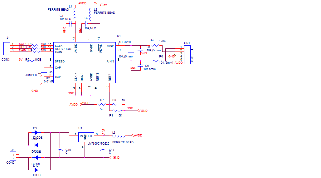
here i used ads1230 ic and pic 18f4550 ic... i finished coding everythik.. Now my problem is i got counts from adc1230..but fluctuation.
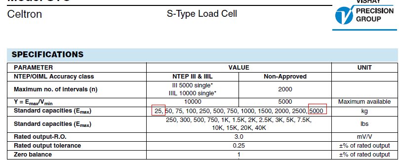
I used S type load cell.rated output is 3mv/V.

pls help me ... what can i do..............


  • Suresh,

    What gain are you using?  What are you using as a reference voltage?  How much code variation do you see?

    It is very important that you bypass the power supplies and have a cap at the REF pins of the ADS1230.  It is also very important that you do not have a noisy power supply, and especially so for the reference.

    You might want to take a look at our reference design user's guide:

    http://focus.ti.com/general/docs/lit/getliterature.tsp?literatureNumber=sbau125a&fileType=pdf

    If you compare your design and ours (including the layout) you may find ways to improve your design.

    Best regards,

    Bob B

  • thank u sir for ur immediate response... now i'm having hard copy only ... i don't have soft copy. today evening i will send soft copy .. and then i compared with ur reference design .. At reference point side i don't use any capacitor...may be thats my problem.....this is my code sir...

    pls indimate to i want change anything

    My code is............. pls sir very urgent ..bcoz one week i waste for this project

    void main()
    {
    unsigned long receive_data_2,offset_data_1,offset_data_2,display_value;
    unsigned char dummy_v,dummy_c;

    Port_Config();
    receive_data_2=0;
    DATA=0;
    TRISB=0x00;
    TRISD=0x40;
    DATA_DIR=1;
    SCLK_DIR=0;
    GRD_DIR =0;
    GAIN=0;


    lcdinit();
    __delay_ms(25);
    lcdcmd(0x01);
    __delay_ms(25);
    lcdstr(home);
    __delay_ms(25);
    lcdcmd(0xC0);
    __delay_ms(25);
    lcdstr(home);
    __delay_ms(25);


    ////////////////////// weight scale initialize////////////////

    lcdcmd(0x80);
    lcdstr("dummy start");
    delay(50);

    for(dummy_c=0;dummy_c<=4;dummy_c++)
    {

    dummy_v=get_adc1230();

    }

    lcdcmd(0x80);
    lcdstr("Offset start");
    delay(50);

    offset_data_1=offset_calibation_adc1230();

    offset_data_2=offset_calibation_adc1230();
    display(0xC0,offset_data_2);
    /////////////////////////////////////////////////////////////////////////

    while(1)
    {
    DATA_DIR=1;
    device_c=0;

    receive_data_2=get_adc1230();
    display(0x80,receive_data_2);


    /*   
           
            if(offset_device_c==1)
            {
           
            __delay_ms(10);
            lcdcmd(0xC4);
            __delay_ms(10);
            lcdstr(dect);
           
            }
            else
            {
           
            __delay_ms(10);
            lcdcmd(0xC4);
            __delay_ms(10);
            lcdstr(ndect);
            }

    */

    receive_data_2=0;
    offset_data_2=0;
    display_value=0;
    delay(60);
    }
    }

    void display(unsigned char pos,unsigned long receive_data_dis)
    {
    unsigned long display_value=0;

    __delay_ms(50);
    lcdcmd(pos);
    __delay_ms(50);


        if ( receive_data_dis < 0x80000 )
        {
        display_value = receive_data_dis >> 1;
        }
        else
        {
        display_value = (( ~( receive_data_dis - 1 ) ) & 0x000FFFFF ) >> 1;      // ¸ºÊý ( È¡19λADÖµ, ÆÁ±Î5λ )
        //display_value = -display_value;
        //ES = 1;                                                                //
        }

    lcdchar(((display_value/10000000)+0x30));
    lcdchar((((display_value/1000000)%10)+0x30));
    lcdchar((((display_value/100000)%10)+0x30));
    lcdchar(((display_value/10000)%10)+0x30);
    lcdchar(((display_value/1000)%10)+0x30);
    lcdchar(((display_value/100)%10)+0x30);
    lcdchar(((display_value/10)%10)+0x30);
    lcdchar((display_value % 10)+0x30);
    }


    unsigned long get_adc1230()
    {
    unsigned long receive_data=0;;
    unsigned char clk=0;

    SCLK=0;
    NOP();
    NOP();
    NOP();
    NOP();


    while(DATA);

    device_c=1;

        NOP();
        NOP();
        NOP();
       
        for(clk=0;clk<=19;clk++)
        {
        SCLK=1;
        __delay_ms(2);

        SCLK=0;
        __delay_ms(2);
       

    /*   
        NOP();
        NOP();
        NOP();
        NOP();
    */              
    receive_data=receive_data<<1;

                if ( DATA == 1 )
                  receive_data|= 0x00000001;//0000 0000 0000 0000 0001
                else
                receive_data &= 0x000FFFFE;//1111 1111 1111 1111 1110
                NOP();
                NOP();
        }


    //DATA_DIR=0;
    //DATA=1;


    __delay_ms(25);
    lcdcmd(0x8D);
    __delay_ms(25);
    lcdchar((clk/10)+0x30);
    lcdchar((clk % 10)+0x30);

    return(receive_data);
    }

    ///////////////////////////////////////////////////////////////////
    ////////////offset calibaration

    unsigned long offset_calibation_adc1230()
    {
    unsigned long offset_receive_data=0;;
    unsigned char offset_clk=0;

    SCLK=0;
    NOP();
    NOP();
    NOP();
    NOP();


    while(DATA);
    //offset_device_c=1;
    NOP();
    NOP();
    NOP();
       
       
        for(offset_clk=0;offset_clk<=25;offset_clk++)
        {
        SCLK=1;
        __delay_ms(2);

        SCLK=0;
        __delay_ms(2);
                  
       
            if(offset_clk<=19)
            {
            offset_receive_data=offset_receive_data<<1;

                if ( DATA == 1 )
                  offset_receive_data|= 0x00000001;//0000 0000 0000 0000 0001
                else
                offset_receive_data &= 0x000FFFFE;//1111 1111 1111 1111 1110
                NOP();
                NOP();

                    if(offset_clk==19)
                    {
                    DATA_DIR=0;
                    DATA=1;
                    //__delay_us(50);
                    DATA_DIR=1;
                    delay(32);
                    }
            }
       
        }


    return(offset_receive_data);
    }


    ///////////////////////////////////////////////////////////////////////////
    // Initialise system
    static void Port_Config(void)
    {
    ADCON1 = 0x0F; // Default all pins to digital see datasheet

    // Configure ports as inputs (1) or outputs(0)
    TRISA = 0b00000000;
    TRISB = 0b00000000;
    TRISC = 0b00000000;
    TRISD = 0b00000000;
    TRISE = 0b00000000;

    // Clear all ports
    PORTA = 0b00000000;
    PORTB = 0b00000000;
    PORTC = 0b00000000;
    PORTD = 0b00000000;
    PORTE = 0b00000000;

    }


    void delay(unsigned int time)
    {
    int i,j;

    for(i=0;i<=time;i++)
    {
    __delay_ms(25);
    }

    }

  • Suresh,

    Please only post your questions on one forum post.  You are welcome to review other forum responses for possible answers, but it gets very confusing trying to answer your questions when you post multiple times.

    You haven't answered my questions, and sending me your code doesn't really tell me anything.  If you are seeing large variations in your readings, this is usually due to noise.  Noise is expected, but can be made worse by noisy power supplies, a noisy reference or poor board layout.

    Your best case noise test is found by shorting the inputs and biasing the shorted inputs to mid-scale supply.  That means if the AVDD is 5V, mid supply is 2.5V.  I've attached a portion of a schematic to help you understand how you might be able to do this.  Assume that the rest of the ADS1230 pins are connected as they are supposed to be and this just shows you how to do the shorted input test.

    Once you have this in place, see how much code variation there is when you read the results from the ADS1230.  Compare the results with Table 1 (or Table 2) of the datasheet.  Best case noise free bits is 18.  If you see something much worse, then you will need to clean up your supplies, reference, or layout to improve performance.

    What are you using for a power supply and a reference supply?

     Best regards,

    Bob B


  • thank u sir for your response. your schematic very helpful to me.I will do that . My power supply (AVDD) and reference voltage(REFP) both are 5.07V

  • Suresh,

    How are you developing the 5V?  If this comes from a switching type of power supply, this can be very noisy.  Are you able to look at your power supply with an oscilloscope to see how much noise and ripple are on your supply?

    Best regards,

    Bob B

  • sir  this is my design ... is it produce any noise ... if it is having any noise ,please tell me which component i have to replace...


  • Suresh,

    I would double check your reference.  Depending on the resistor tolerance, you could be very close to the reference minimum of 1.5V.  Also, you need to be very careful about temperature drift with these resistors as well.  It would also be a good idea to place a capacitor as close as you can to the REFP pin to ground.  The value of this cap should be a minimum of 0.1uF up to about 10uF.  This will help to stabilize the reference to make sure there is sufficient charge available when sampling the reference. 

    Also make sure that C3 and C5 are high quality caps, like C0G.  You also need to have a good ground plane and not just ground traces.  Ground traces can act like a small antenna and pick up RF or EMI noise.

    Best regards,

    Bob B

  • thank u sir for your valuable answer.here i attached my load cell specification. They are giving 3mv/V.load capacities is 25kg to 5000kg.For examble if i'm applying 10V excitation,my rated value is 3 * 10v=30mv.when i place 5000kg on the load cell,the output of the load cell value is 30mv ...is it correct sir ?  or .when i place 25kg on the load cell,the output of the load cell value is 30mv ...........i just marked red color rectangular box in the picture.

  • Suresh,

    You buy a load cell based on the maximum value you want to measure, so it depends on which load cell you purchase.  So which load cell capacity do you have?

    Your schematic shows AVDD as 5V, so let's use that voltage and I'll assume you are using the 25kg load cell.  Maximum deflection of the load cell will be as you said.  5V (excitation) * 3mV/V = 15mV will result when 25kg is placed on the load cell.  In this case you can use the GAIN of 128 for best scale as it allows a differential input of +/- 19.5mV if you use the excitation voltage (AVDD) as the reference. 

    If you reduce the reference voltage, you will reduce the full-scale input range (+/-0.5VREF/PGA (GAIN)).  As the reference in your schematic is 1/3 of AVDD (1.67V) you will need to recalculate this so with a GAIN of 128, the full-scale range is +/-6.5mV.  At a GAIN of 64, the full-scale input range is +/-13mV.  Neither of these two gains will allow the full deflection of the load cell as they do not reach 15mV.  So I would suggest that you use AVDD (5V) as the reference, and set the GAIN for 128.  This would eliminate the voltage divider and associated issues at the reference.

    Now the big difference you will see due to capacity from load cell to load cell is resolution (LSB size relative to the capacity) and how noise will affect the overall results.  As you might imagine, the higher the load cell capacity, the more the noise will affect the accuracy of the reading.  In any case, with a VREF of 5V and GAIN of 128, one LSB ( or single count) is equal to (0.5(AVDD)/GAIN)/(2^19 - 1) which is about 37nV. 

    If we take the maximum input of 15mV and divide by the LSB size of 37nV, we get a maximum count of 405, 405.  Then if we take the capacity of the load cell and divide by the maximum count (25kg/405405) we get a result of 0.0617g per code (count).  Remember that so far we are not including any variation due to noise.  Noise will fluctuate the readings at 10sps and GAIN of 128 by 5 to 6 codes within the converter itself (this excludes any noise externally.)  So with a very quiet system, and using the 25kg capacity, the result will fluctuate by 2-3 bits.

    Now if you go to the 5000kg capacity, one LSB will be 12.3 g.  So even in the best case you can not achieve 1 gram resolution.  So the lesson to learn here is only use the capacity of load cell that fits the requirement.  Using a larger capacity load cell than you need will affect your level of performance and limit your ability to resolve small loads.

    In any case, you will need to consider noise and what it does to your overall ability to read stable data.  Please review the application example on page 20 of the ADS1230 datasheet where it talks about noise free counts and how to calculate them.  You will notice that the total noise free counts will be more like 142,500 and not the theoretical value we used earlier.  In other words, it is much worse.  In fact, even with this calculation it is assumed that some filtering or averaging is being done outside of the converter.

    Best regards,

    Bob B

  • hai,

       iam praveen ,now iam workin in marc weighin system kerala, india.we are the manufacture of weighin machine.in our new design we using adc 1230 ic .it  works properly and good stability is their .

    our problem is the mobile radiation will lead to some fluctuatiomns in the reading.

    1. what are factors affecting mobile radiation

    2. how it will solve 

    i expect a replay 

    thankyou