This thread has been locked.

If you have a related question, please click the "Ask a related question" button in the top right corner. The newly created question will be automatically linked to this question.

ADS1278: Random startup offset

Part Number: ADS1278

Hi,

I am working with ADS1278.

Configuration is
Low power mode, SPI, TDM, FIXED
CLK = 25 MHz
SCLK = 25 MHz
DRDY = 48 kHz

The problem is in random offset (+-100 lsb) at power on and / or CLK restart.

After some experiment I've found that
1. Offset appears after stop / start timer in microcontroller which used to generate CLK
2. Offset doesn't apper after enable / disable gpio on CLK pin while timer running

Is it normal behavior?

  • Hello Alexander,

    Welcome to the TI E2E community.

    The ADS1278 requires a continuous CLK for proper operation.  After power-up, or changing the CLK frequency, you should assert the /SYNC pin after the first DRDY.  This has the effect of a hardware reset, and will return the ADS1278 to normal operation.

    Regards,
    Keith Nicholas
    Precision ADC Applications

  • Hello Keith,

    thanks for the answer.

    A few clarifications.

    1. In experiment from my question I don't change frequency of CLK (just stop / start CLK).

    2. The datasheet (page 27) says that ADS1278 can be (not must be) synchronized. As I understand it, internal channels "are always in synchronization with each other. The aperture match among internal channels is typically less than 500ps". /SYNC pin designed for external synchronization and reset internal digital filter.

    How important re-assert /SYNC after fisrt (not second, third and so on) DRDY? Should I observe the timing diagram at figure 73?
    The hardware design doesn't allow synchronize SYNC pin with CLK with nanosecond precision.

    I've try re-assert /SYNC but it has no effect.

    I have attached some image. This is data from one ADC channel. N and P pins are shorted to GND. One point is 1 second average. Ignore the spikes - it's CLK stop/start.

    Offset appears after stop / start timer in microcontroller which used to generate CLK


    Offset doesn't apper after enable / disable gpio on CLK pin while timer running


  • Hello Keith,

    thanks for the answer.

    A few clarifications.

    1. In experiment from my question I don't change frequency of CLK (just stop / start CLK).

    2. The datasheet (page 27) says that ADS1278 can be (not must be) synchronized. As I understand it, internal channels "are always in synchronization with each other. The aperture match among internal channels is typically less than 500ps". /SYNC pin designed for external synchronization and reset internal digital filter.

    How important re-assert /SYNC after fisrt (not second, third and so on) DRDY? Should I observe the timing diagram at figure 73?
    The hardware design doesn't allow synchronize SYNC pin with CLK with nanosecond precision.

    I've try re-assert /SYNC but it has no effect.

  • Hello Alexander,

    The internal ADC's are always synchronized with each other.  However, after a power-on reset (or changing one of the pin configurations or CLK) it is recommended to do a single /SYNC pulse to reset the device.  After the clock and power supply rails have stabilized, you only need to assert /SYNC 1 time.  The nS timing requirements between the SYNC edge and CLK are only important if you need to synchronize multiple ADS1278's to the same exact clock edge.

    Can you capture the CLK signal just before and after enable to confirm that it is steady?  Normally, we do not recommend driving the CLK pin from a timer resource as this introduces a lot of jitter, reducing the performance of the ADC.  It is best to have a continuous running CLK from an oscillator or dedicated clock PLL circuit that provides an adjustable frequency control.

    Regards,
    Keith

  • Hello Keith,

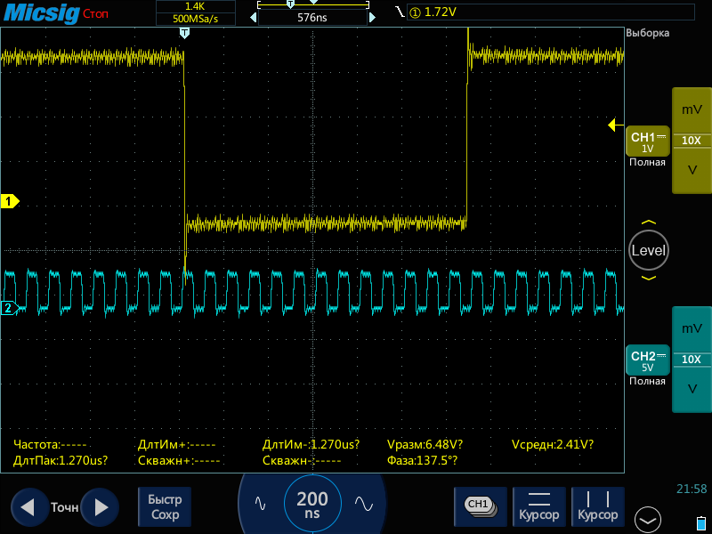
    I've connect CLK to external oscilator. Then, after power up I've done single /SYNC pulse. See capture below (yellow -- SYNC signal, blue - CLK).

  • Hello Alexander,

    Based on the above waveform, it appears that you have met all timing requirements for a correct Synchronization (reset).

    Regards,
    Keith

  • Hello Keith,

    yep. But random offset appears between power on / off (not matter /SYNC pulse) and between /SYNC pulses (when CLK stable). Is it correct behaviour?

  • Hello Alexander,

    No, this is not normal behavior.  Using the ADS1278EVM, I cycled power multiple times.  In each case, with shorted inputs to GND, I measured a code between 250 and 270.  This was the mean of 10,000 samples to reduce the noise.

    This could be a hardware layout issue.  Are you using the EVM board, or is the ADS1278 on your own custom board?  If so, are the AGND and DGND pins on the ADS1278 connected to the same ground plane on your board?  Do you have power supply bypass capacitors for each of the power pins?

    Regards,
    Keith

  • Hello Keith,

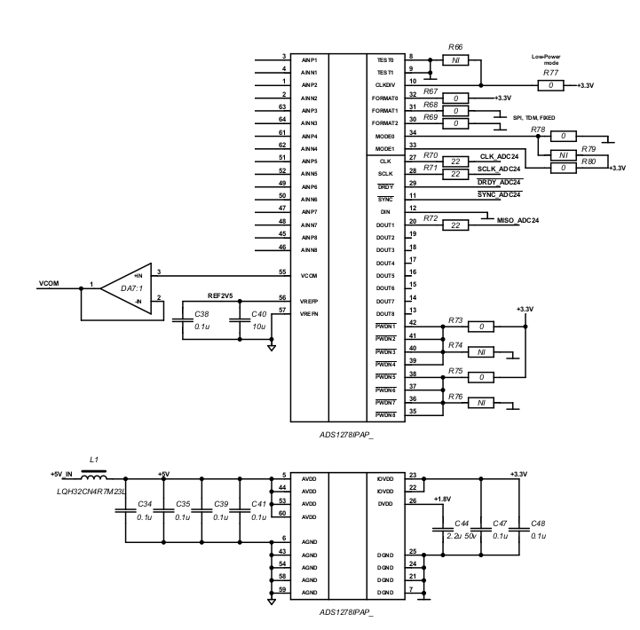
    I am using ADS1278 on custom board. AGND and DGND connected to different ground. Capacitors for power pins are installed. See shematic below

  • One more addition after consultatioun with hardware engeneer. AGND and DGND connected together at some point on board. From ADS1278 its two independent lines stretch, which will connect somewhere at a point. Should they be connected as closely as possible near the ADS1278?

  • Hello Alexander,

    I did some more tests on the evaluation board.  There is a dependence on offset voltage based on how many channels are enabled.  I could power-cycle multiple times on the same channel, and the mean value would change less than 10 counts (Using a 2.5V reference, this is equivalent to 3uV change.)  Enabling all channels and then measuring a single channel, the offset would jump by about 80 counts, or 24uV.

    I am not certain if your grounding arrangement could be showing up in the offset, but you need to change the grounding for reliability.  The two grounds should be connected to the same ground plane directly beneath the device for best performance.

    Yes, the two grounds of the ADC need to be connected together as close to the device as possible.

    Regards,
    Keith

  • Hello Keith,

    After several days of research, I came to the conclusion that these offsets are related to the phase between SCLK and CLK. After I clocked SCLK from HSI and CLK from HSE the offset disappeared.