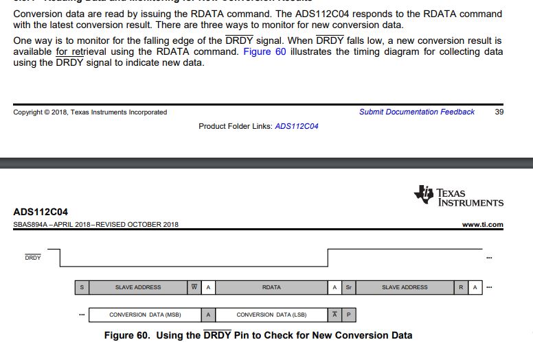
This thread has been locked.

If you have a related question, please click the "Ask a related question" button in the top right corner. The newly created question will be automatically linked to this question.

ADS112C04: How to read the data from each channel in the ADS112C04

Part Number: ADS112C04

Hello..

I want to know how to read the data from the ADS112C04 ADC. First, I have given the slave address as 0X80, and after START/SYNC command as 0x08. what should I do after doing this I want to read the data continuously from the ADC channels.  After giving the START/SYNC what should i send to ADC to read the 16-bit values of each channel connected to ADC.

Regards,

Nareshreddy

  • Hi Naresh,

    There are actually a number of ways to do this, so it would be helpful to know how you are intending to configure the ADS112C04 and what you are trying to measure.  The default configuration places the input to the AIN0 and AIN1 inputs, operates in single-shot mode, conversion is at 20sps, using a gain of 1 with the internal reference.

    After the the START command is issued, approximately 50ms later the conversion will complete which is signaled by the DRDY pin going from a high to low state.  At that point the ADC will stop converting and will wait for you to read the result by issuing the RDATA command.  After you have read the conversion data, you can change the input mux to a different channel and issue the START command again following the same process as before.

    Best regards,

    Bob B  

  • Hello Bob b..

    Thank you for replay back to my issue.

    If I select conversation mode as continuous conversation whether the ADS112C04 will send the channel AIN0 to AIN3 data continuously (like auto-scan mode).

    if i write the ADS112C04 with 0x80 ,0x40 , 0x00 --configure register 0x00h

    if i write the ADS112C04 with 0x80 ,0x44 , 0x08 --configure register 0x01h

    if I read the ADS112C04 with {0x81,0x10,----,----}  the ADS112C04 will give the channel AIN0 data and followed by the remaining channels.

    Regards,

    Nareshreddy

  • Hi Nareshreddy,

    The ADS112C04 does not have an auto-scan feature nor is there a FIFO memory.  Each input channel must:

    • first be selected,
    • the end of conversion detected,
    • and the conversion data read from the device. 

    This action is required for each input channel desired. 

    Best regards,

    Bob B

  • Hello..

    If auto-scan feature is not there in ADS112C04 then what is continuous conversation mode and Single-shot conversion mode ?

    Regards ,

    Nareshreddy

  • Hello..

    If want to read each channel individually what data I need to send to ADC.

    AIN0---

    AIN1---

    AIN2---

    AIN3---

    Regards,

    Nareshreddy

  • Hi Nareshreddy,

    I would refer you to the ADS112C04 datasheet for details regarding continuous conversion and single-shot modes of operation.  Basically continuous mode refers to continuous conversions of the selected mux channel.  Once a conversion completes another conversion is started automatically.  For single-shot mode only one conversion for the selected mux channel completes and then the ADS112C04 will go to a low-power state.

    Best regards,

    Bob B

  • Hi Nareshreddy,

    I explained this process previously and will attempt to do so again with a little more detail.  I assume that when you say you want to measure AIN0 you really want to measure AIN0 to AVSS as the mux selection.  For this discussion we will use the default register settings for all but register 0.  To make single-ended measurements referenced to AVSS (AGND) you need to disable and bypass the PGA (bit 0 should be set to 1) in register 0.

    • AINP= AIN0 and AINN= AVSS must first be selected in configuration register 0.  The mux selection bits (MUX[3:0]) are bits 7-4 of register 0.  AIN0 to AVSS is 1000b and the value for register 0 would be 10000001b or 0x81.  You need to send the WREG command for register 0 which would be 0x40 0x81
    • Write the START command 0x08
    • Monitoring DRDY going from high to low state,
    • and the conversion data read from the device using the RDATA command by writing 0x10 then reading 2 bytes of data. 

    You would repeat this process for the other channels:

    • Set the mux to AIN1 by WREG 0x40 0x91
    • Set the mux to AIN2 by WREG 0x40 0xA1
    • Set the mux to AIN3 by WREG 0x40 0xB1

    Please review the ADS112C04 datasheet for specific details on how to accomplish the various operations.

    Best regards,

    Bob B

  • Hello Bob B ..

    I write the code according to the datasheet. I have one doubt if I need to read the data in continuous conversation mode I need to monitor the DRDY input.

    Please let me know could I start the data read. In the datasheet, they mention like Whenever DRDY goes LOW indicates new data available. 

    Whether I need to send the start and followed command only when DRDY when to LOW? 

    When the DRDY goes high? because in the datasheet it is showing RDATA 'A' bit DRDY going HIGH state.

    If I write like below 

    • Set the mux to AIN1 by WREG 0x40 0x91
    • Set the mux to AIN2 by WREG 0x40 0xA1
    • Set the mux to AIN3 by WREG 0x40 0xB1
    • Set the mux to AIN3 by WREG 0x40 0x81

    if I am Written WREG 0x40 0X81 and I gave stop. Now I need to wait until the DRDY goes low to measure the CH0 data for giving the commands 0x80 0x10 0x81 {-----------} ,{-----------} for data corresponding CH0 .

    How could i give the command to read if DRDY goes LOW only i need to give the command for read ?

    After reading one channel data again i need to write one more channel and wait until the DRDY goes low ?

    Regards,

    Nareshreddy

  • Hi Nareshreddy,

    Although you can operate in continuous conversion mode, it may be easier to keep the conversions from overlapping if you use the single-shot mode instead.  In continuous conversion mode writing a new mux configuration will restart the conversion with the new configuration, but using this mode you will need to make sure that you keep track of the conversions and the time they are ready to read.

    In single-shot mode you control when you want to start the conversion as well as when you want to read the result.  In this way it is a little easier to program the loop.

    In pseudo code with single-shot mode the code flow would appear something like:

    While (.t.)

    {

    1. Send the WREG command to set the mux to AIN0-AVSS
    2. Send the Start command to start the conversion for AIN0
    3. While loop for DRDY high and exit the loop when DRDY goes low
    4. Issue the RDATA command and read the result for AIN0
    5. Send the WREG command to set the mux to AIN1-AVSS
    6. Send the Start command to start the conversion for AIN1
    7. While loop for DRDY high and exit the loop when DRDY goes low
    8. Issue the RDATA command and read the result for AIN1
    9. Send the WREG command to set the mux to AIN2-AVSS
    10. Send the Start command to start the conversion for AIN2
    11. While loop for DRDY high and exit the loop when DRDY goes low
    12. Issue the RDATA command and read the result for AIN2
    13. Send the WREG command to set the mux to AIN3-AVSS
    14. Send the Start command to start the conversion for AIN3
    15. While loop for DRDY high and exit the loop when DRDY goes low
    16. Issue the RDATA command and read the result for AIN3
    17. Loop back to beginning (1)

    }

    That is the basic flow.  There are some variations that can be done to speed the loop up, but this single-shot mode works well for making sure that every conversion is read at the proper time.

    Best regards,

    Bob B

  • Hello Bob..

    Thank you for replying back to my query.

    I written the code as like below 

    1. Send the WREG command to set the mux to AIN0-AVSS 0x80 0x40 0x81 and i given stop  . Shall i wait until the DRDY goes low for sending start followed by command 0x80 0x10 0x81 {__________} ,{_________} data read ?

    Regards,

    Nareshreddy

  • Hi Nareshreddy,

    I can see now why this may be a bit confusing.  There are I2C communication S (start condition of I2C communication), Sr (repeated start for I2C communication) and P (stop condition for I2C communication).

    There are also commands for the ADS112C04 itself that include the START/SYNC command (which will start conversions in single-shot mode or restart conversions in continuous mode), the WREG (write the ADC register), the RREG (read the ADC register) and the RDATA command (read the last completed conversion result).

    Each of the ADC commands must be framed by the I2C communication.  For example:

    <S> 0x80 0x40 0x81 <P>  // WREG command to set the mux

    <S> 0x80 0x08 <P>           // ADC START/SYNC conversion command

    Monitor DRDY and wait for DRDY to transition from high to low

    <S> 0x80 0x10 <Sr> 0x81 {MSB byte} {LSB Byte} <P>  // RDATA command and data returned from ADC

    I hope that makes it a little more clear.

    Best regards,

    Bob B

  • Hello Bob B..

    Thank you for replay back to my email..

    Now i am able to get the ACK from the ADS112C04 . every command which i wrote .

    steps i am following :

    1.reset the ADS112C04 by issuing below command

    <S>0x80 0x06 <P>

    2.i am tring in the single-shot mode it is set as diffault.

    3. i am writing to ANI0 by follows

    <S> 0x80 0x40 0x81 <P>  // WREG command to set the mux

    <S> 0x80 0x08 <P>           // ADC START/SYNC conversion command

    Monitor DRDY and wait for DRDY to transition from high to low

    <S> 0x80 0x10 <Sr> 0x81 {MSB byte} {LSB Byte} <P>  // RDATA command and data returned from ADC

    4.after read command i am sending for AIN1

    <S> 0x80 0x40 0x91 <P>  // WREG command to set the mux

    <S> 0x80 0x08 <P>           // ADC START/SYNC conversion command

    Monitor DRDY and wait for DRDY to transition from high to low 

    5.after read command i am sending for AIN2

    <S> 0x80 0x40 0xa1 <P>  // WREG command to set the mux

    <S> 0x80 0x08 <P>           // ADC START/SYNC conversion command

    Monitor DRDY and wait for DRDY to transition from high to low 

    6.after read command i am sending for AIN3

    <S> 0x80 0x40 0xb1 <P>  // WREG command to set the mux

    <S> 0x80 0x08 <P>           // ADC START/SYNC conversion command

    Monitor DRDY and wait for DRDY to transition from high to low 

    after last channel again i am repeating the step 3 .

    But for me DRDY pin is not moving to High to LOW . it always high only .


    Regards,

    Naresh reddy