This thread has been locked.

If you have a related question, please click the "Ask a related question" button in the top right corner. The newly created question will be automatically linked to this question.

ADS54J60: Problem with obtaining SFDR values

Part Number: ADS54J60
Other Parts Discussed in Thread: LMK04828

Hi Team,

Can you please check and advise with following request:

"

I would like to ask a few questions about TI's ADS54J60 chip, if possible. We have a problem with obtaining SFDR values which are denoted in ADS54J60 datasheet.

 - We use 250 MHz ADC reference clock, which is the output of LMK04828 chip.

- SYSREF pulses are generated using LMK04828 either. We calculated the SYSREF frequency from SYSREF = LMFC / 2^N. By selecting N=4, (fs/4)/K => (1000/4)/16 = 3.90625 MHz.

- We use 4244 LMFS configuration and corresponding DDC mode & JESD link properties given in datasheet. You can find our register configurations attached (adc_config.txt).

- Fs/4 noises seem acceptable (approximately ~90dBFS).

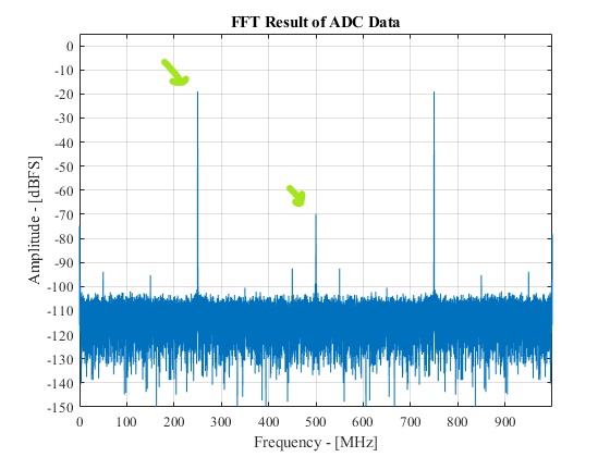
 However, our SFDR is not as fine as datasheet offers. Even if a 0 dBFS signal is applied, our maximum SFDR is around 53 dB. We always observe a harmonic spur (I think it is a second harmonic, aliased somehow) which has 2x bandwidth of original signal.

 I also attached the spectrums of ADC output signal. Do you have a suggestion to improve our SFDR performance? I can provide additional information about out setup if it is required.

 We have a secondary problem, last two LSB output bits of "channel A" are stuck. Depending on the input signal frequency, it is always stuck at some value ("00","01"..). Am I missing something in register configuration?

"

Thanks in advance

Best Regards

Furkan Sefiloglu

  • Furkan,

    What tones are you testing at? The device will saturate with 0dBFs inputs. Are you using bandpass filters with the analog input? All data sheet numbers are taken at -1dBFs. Please send your register settings. 

    Regards,

    Jim 

  • Hi Jim,

    Please see feedback below and attachments:

    "

    - 500MHz to 1000MHz single tone frequencies are tested (Output of analog signal generator - Agilent N5171B), no bandpass filters are used with the analog input.

    - Spectrum outputs for input frequencies of 650MHz, 700MHz, 750MHz are attached (-20dBFS).

    "

    Thanks in advance

    Best Regards

    Furkan Sefiloglu

    000081
    	wait 3x1msec (internal logic)
    001180
    005920
    004F00
    00200F
    0021C0
    0023F0
    002430
    002640	powerdown configs
    005500	powerdown configs
    400100
    400200
    400300
    400468
    60F701
    	wait 3x1msec (internal logic)
    400501
    604EA0	Nyquist EN & Improve IL Perf
    604201  Nyquist Zone A
    704EA0  Nyquist EN & Improve IL Perf
    704201  Nyquist Zone B
    400500
    604420  Digital Gain to 0 dB
    605201
    600001
    600000
    	wait 3x1msec (internal logic)
    400469	
    600200	ADC Test mode off
    600500  Scrambling off
    600709
    600102	Mode 4244
    603100 	Mode 4244
    603200  Mode 4244
    601680
    40046A
    601202
    601602
    601740
    601700
    400468
    604100  Mode 4244
    604D00  Mode 4244
    607200  Mode 4244
    605201  Mode 4244 & Gain Enable
    600001
    600000
    400469
    600080
    60060F  K = 15 
    	wait 4x1msec (internal logic)
    

  • 650MHz input tone.pptxFurkan,

    The register settings look Ok except for address 0x005500. If they want to turn off CHB this needs to be set to 0x10 not 0x00 as they have it. They need to capture data using a bandpass filter as I think this is their issue. Attached is data captured I did from home without a filter. If I had a filter, you would have seen a big improvement. Not sure how noisy their source is. The next time I get a chance to go to the lab, I will duplicate this test with a filter.

    Regards,

    Jim

  • Hi Jim,

    I have posted this question to Furkan. Thank you for your answers.

    Actually, I forgot to say, we are using a balun for the ADC input (MABA-011047. 1:1, Transmission Line Balun, 4.5 - 3000MHz). Maybe we should change it to have a max. frequency of 1000MHz.

    Very appreciate your help.

    Kind regards,

    Dogancan

  • Dogancan,

    I think this transformer is ok to use. Using a transformer with a max frequency of 1000MHz will still pass higher frequencies'. They will just start to attenuate as you go up in frequency. I would try the bandpass filter first. 

    Regards,

    Jim

  • Hi Jim,

    You were right, bandpass filter has solved the problem. Now, SFDR performance matches the product specification.

    Thank you!

    Dogancan