This thread has been locked.

If you have a related question, please click the "Ask a related question" button in the top right corner. The newly created question will be automatically linked to this question.

ADS1235: ADS1235 not running at desired speed.

Part Number: ADS1235
Other Parts Discussed in Thread: , ADS1232

Greetings I have ADS1235 evb and recently i have found that ADS1235 is not running at set speed.

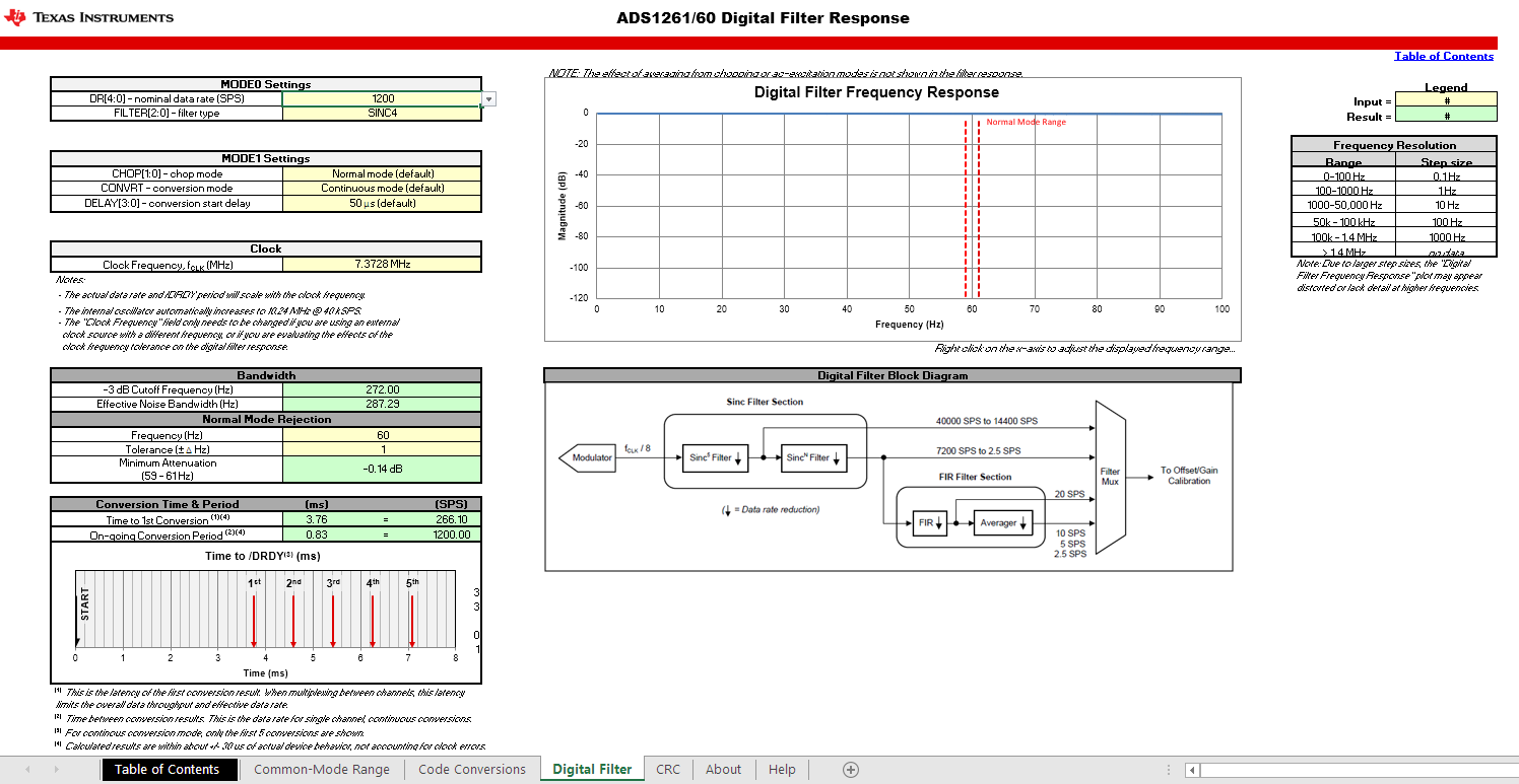
I am setting ADS1235 with 1200 samples per second speed and conversion delay is 50uS. According to data sheet it should give me atleast 1000/3.758 = 266 samples. 

I have a free running timer in my micro-controller which stops after every 1 second. While the timmer is running i am getting samples in an array and it is always 63 counts. What wrong i am doing ? Please guide me..

  • Hi Nimit,

    You state you are using the ADS1235EVM, is that correct?  And you are connecting the EVM to an external controller, is that correct?  You should monitor DOUT with an oscilloscope or logic analyzer to verify the conversion timing.  Can you send the configuration register settings you are using?

    Best regards,

    Bob B

  • Greetings Bob,

    Yes, I am connecting ADS1235 EVM to an external controller. I have put evm board to reset mode so that on board controller doesn't work.

    Below are my settings 

    1. Mode0 - 1200 sps and Sinc4 is on.
    2. Mode1 - Chop is off and continuous conversion with delay of 50uS.
    3. REF MUXP is REFP0 and REF MUXN is REFN0.
    4. GAIN OF 128.
    5. INPUT  - INPMUX_MUXN_AIN1 and INPMUX_MUXP_AIN0

    I was wondering in this mode what is the clock input for ADS1235 ?

  • Hi Nimit,

    I still don't have all of the information regarding your setup.  For example, do you have any connection from your micro to the CLKIN, START, RESET and PWDN pins?  Or are you just using the default conditions of the EVM hardware?

    The CLKIN pin defaults to low, so as long as nothing is connected to this pin then the internal oscillator is connected and the typical frequency is 7.3728MHz.  All of the timing table information is based on that frequency.

    There is a calculator tool for the ADS1260-61 which uses a similar timing as the ADS1235.

    https://www.ti.com/tool/ADS1261-EXCEL-CALC-TOOL

    I have added a screen shot below of the timing for the settings you are using:

    If you monitor DRDY with an oscilloscope of logic analyzer you can verify the timing on the EVM for the settings you are using.  The result should match what is shown above.  If the ADS1235 data rate is as shown, then there is something at issue in the reading loop of your micro code.

    Bests regards,

    Bob B

  • Greetings Bob,

    Thanks for the tool. I will look up and get back here. 

  • Well for more clarification from my side i have connected these pin to my controller

    1. DRDY
    2. SCLK
    3. CS
    4. DIN
    5. DOUT
    6. RST

    I have shorted JP1.

    Is my connection okay ?

  • Hi Nimit,

    So the CLKIN pin will be pulled low and the internal oscillator will be used.  At this point I can only assume that either the ADS1235 is configured incorrectly or you are not capturing the conversion data for every completed conversion.  When writing the configuration registers, have you read them back to verify that the contents were properly written?

    Please send me oscilloscope or logic analyzer shots of the communication for me to verify.  The shots should include CS, DIN, DOUT and SCLK as a minimum.  It would also be helpful to see DRDY to verify the actual conversion data output rate. I need to see the time between DRDY high to low transitions.

    I really can't help you further without knowing specifically the data you are writing to the ADS1235 and verifying the communication with the scope/logic analyzer shots. This means that I need to see what is actually being sent to the ADS1235 as opposed to "Mode0 - 1200 sps and Sinc4 is on."  

    Best regards,

    Bob B

  • Okies,

    As you have pointed, "CLKIN" is not changed. I have kept it as it is. After tying EXT_CLK to DVDD the ADC doesn't respond. Do i have to remove R47 ?

    Edit to the above statement : I did it wrong. I need to tie it to GND... I corrected my connection..Then at MODE0_DR_1200_SPS and SINC4 still i am getting 125 samples per second.. I have also rechecked all the parameters that i am writing to ADS1235 and all are correct i.e. ADS1235 sends me the values that are written.  

  • Hi Nimit,

    Can you please send me scope or logic analyzer shots of the communication and the DRDY signal?  125sps is not a configuration option. 

    How are you determining that you are only getting 125sps?  You must monitor DRDY to determine the data rate.  You cannot determine this by only retrieving the conversion data in your code as your code may have issues.

    What is your SCLK speed of your micro?

    Best regards,

    Bob B

  • Greetings Bob,

    I am very sorry to bug you like this. Well as per your advice the problem is found. 

    1. First of all i was keeping Ext_Clk of EVM floating. Then i connected it to DGND
    2. STR was floating or not connected, so i connected it to DVDD and as i have said i am running in continuous sample mode. 
    3. removed some delay routine from my side of programming

    After doing above steps... Bang. It started giving me number of samples as per the data sheet. First two issues were major.

    Thanks anyways for helping me out.

    Note: I don't have any scope to send you the pictures, but in near future i am getting one scope.

    Thanks again.

  • Hi Nimit,

    I'm glad to hear that you found your issues and were able to get things working.  Just as a point of clarification, the ADS1235EVM has pullups and pulldowns on various pins as shown below. 

    Note that unless the resistors have been removed, the START, RESET and PWDN pins are pulled to DVDD and the CLKIN pin is pulled low.

    Best regards,

    Bob B

  • Greetings Bob,

    I have one more question .. As per data sheet if we use this adc at low sample speed we tend to get more accuracy correct ? Since many years i am trying to achieve 500,000 counts of accuracy or internal resolution. Can you please guide me how to achieve that sort of resolution using this ADC. 

    I am ready to fire a new question but after your reply on this.

    Thanks.

  • Hi Nimit,

    100,000 counts is difficult to achieve let alone 500,000.  The ADS1235 (and any other ADC) will be limited based on the conversion noise of the ADC.  This will include the PGA and quantization noise.  To achieve the lowest noise with the least amount of drift issues will require that the measurement be made ratiometrically where the excitation of the bridge and the reference voltage to the ADS1235 are the same.  The excitation/reference noise and drift cancel using this configuration.

    Looking at front page of the ADS1235 datasheet you will see a bullet item where it is stated that you can achieve 120,000 noise-free counts with a 10mV/V input and 10sps data output rate.  The application information to achieve the 120,000 noise-free count is given in the ADS1235 datasheet in section 9.2.

    It is possible to achieve greater resolution based on data rate, gain and the digital filter being used.  To achieve 500,000 noise-free counts will depend on the sensitivity of the bridge.  A 1mV/V sensitivity will have fewer noise-free counts and 3mV/V will have more noise-free counts.  The reason for the difference in counts is due to the full-scale output of the bridge relative to the full-scale range of the ADC.

    These calculations are of course only with respect to the ADC and ideal conditions.  The calculations do not take into account any effects of the sensor itself or noise pickup due to EMI and RFI.

    Let's look at a different perspective,  If the sensitivity of a load cell is 2mV/V and the excitation voltage is 5V, the maximum voltage output of the load cell is 10mV.  If the load cell is 50kg and you want to have stable and accurate measurements of 0.1g, then you would need 500,000 noise-free counts.  What you are asking of the ADC is to resolve 10mV/500,000 counts or 20nV noise-free.  That is 0.00000002 V.  If you look at the noise table in the ADS1235 datasheet you need to find the data rate, filter and PGA setting that can resolve to this level such as 2.5sps, Sinc4 filter and Gain of 128.  There may be some other ways of improvement such as using a moving average at higher data rates that might also give you similar results, but remember this is only the best that the ADC can do and is not a reflection of the actual results you can achieve.

    If your sensitivity is lower, such as 1mV/V, the voltage resolution requirement would become 10nV noise-free.  So it is not easy to give a quick answer on how to make settings on the ADC give you the result you desire.

    What I have seen in most systems are issues with external noise primarily picked up in cabling.  Power line-cycle noise is the most common.  This requires that cabling from the sensor to the ADC be shielded and properly terminated.

    Best regards,

    Bob B

  • Greetings Bod,

    Well all my implementations are ratio metric i.e. 6 wire load cell. E+, E-, S+, S-, Sense + and Sense -.

    Next part that you have mentioned regarding ADC and load cell sensitivity, agreed on it. Now I have one working circuit that has ADS1232 and Renesas 16 bit micro-controller that gives 10000000 counts of resolution. Any idea..

  • Greetings Bob,

    Please ignore my above post. Now i know what actually i am looking for. I am looking to scale the load cell readings to 500,000 counts. Well after reading your post i saw several other articles stating the difference between accuracy and resolution.  So i am looking to scale the accuracy of the readings several times.

    Thanks and please ignore my above post.