This thread has been locked.
If you have a related question, please click the "Ask a related question" button in the top right corner. The newly created question will be automatically linked to this question.
Hi,
I am still playing around with that DAC0800 ( actually with good results ) however I have a small problem that I am not sure which one is the best way to fix it so before I try something I decided to post here.
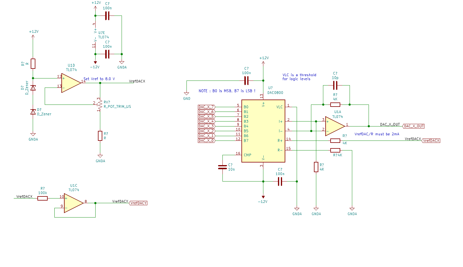
So I am using the following circuit ( designed to have a swing between +8 and -8 V DC )
The "4K resistors" in reality are 2x 2K 1% resistors in series.
Now of course, tolerances and such, the output is NOT 100% symmetric, i.e. the output at code 00H is not precisely the negative of the code at FFH there's a small difference.
Question is, how do I make those two codes be PRECISELY ( or as much precise as possible ) close to be +Vref and -Vref ( and or I'd be even "ok" to be +Vref-err and -Vref-eff as long as they are as much symmetric as possible ) ?
Should I try by putting a trimmer in place of the R ( I should have named them sorry, let's call it Rf ) between pin 2 and 1 of the op-amp ( that should control the gain ) and/or in place of the R between pin 3 and GND of the op-am ( let's call it R1 ) that should also someway control the gain but also the "offset".
As an inverting amplifier the gain should be -Rf/R1 but I am guessing "even if I touch the gain that won't change the symmetry" ?
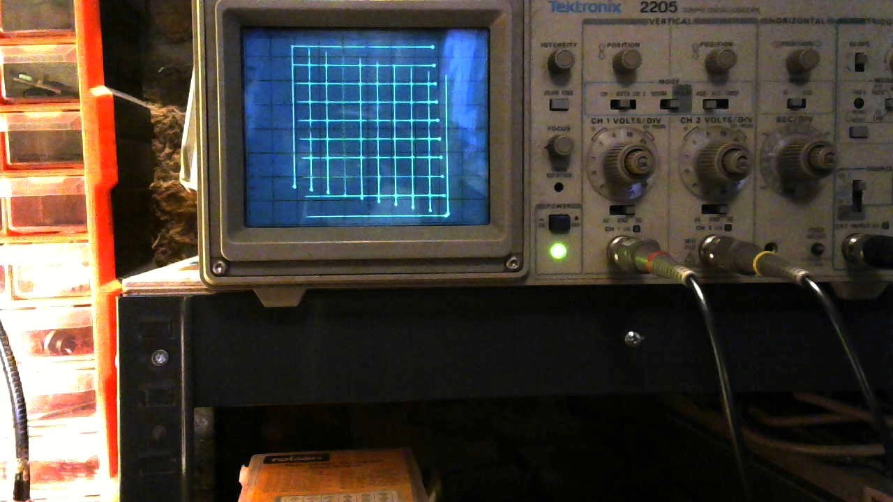
The problem this "missing symmetry" is causing me is visible in this next pic, after LOT of measuring and other tests I am 99% confident it's due the fact that when I move from +X/+Y to -X/-Y I don't return to the same place but there's a constant error that gets added up ( this because I am moving +/- in X with a constant step Y ).
To be honest the non-symmetry ( I should have checked in advance ) can be easily spotted measuring with a volt-meter directly at the DAC output and even just like that you see it's not perfectly balanced.
Anyway thanks in advance for any help.
Cheers.
Hi,
sorry, my fault, overlook, I just realised that is NOT an "inverting amp".
Anyway still trying to understand how to make the output as close as possible to symmetric.
[edit] - actually I may have found the answer myself, but if someone here could confirm me that is a correct solution would be nice :)
I found this "Application Note" from National Semiconductors : AN-0597 which basically says at some point " Due to inaccuracies of resistors and offset voltage in the amplifier the circuit will need trimming. This is accomplished by setting the maximum output voltage to +3V (logic inputs HIGH), and the minimum output voltage -3V (logic in-puts LOW). R1 will change the reference current IREF and with it both extremes of the output voltage. The resistor R7 will influence only the negative extreme."
Basically at pin 14 "Vref Input" they add a trimmer they call "R1" and that R in my schematic from pin 2 of the DAC to GND is what here they call "R7", I'd put the link to the whole PDF but it seems I can't put URLs in this post ( the whole document is called "Current Feedback Amplifiers Application Note 597" June 1989 ).
( Of course their article talks about one of their applications where they configure a +3/-3 swing ).
Cheers.
Hi Ivan,
I found the article you mentioned and this would be a good solution for what you're looking to do. The op-amp used in the article had an internal feedback resistor of 1500 ohms. You may also add a trim resistor to your 4k feedback resistor since it is not internal.
Adding the trim resistor to the feedback should influence the positive extreme as can be seen from the first VOUT equation in the snapshot below.
Let us know if you have any further questions. I'll link the article here for reference.
Hi,
sounds good, if you don't mind waiting a couple of days until I have time to solder the trimmers and do a test so we could confirm 100% that is the solution that works :)
Then we could close the issue and say "yes it really works" :)
Hi Ivan,
Not a problem. Just respond here after you perform your test and we'll go from there.
Hi,
I can confirm that solution as stated in that Application Note works PRECISELY as such :)
By replacing two resistors as they say with two trimmers you can control the output at 00H and FFH and make it precisely the same.
Unfortunately I had a "disaster strike" during the week end ( that has nothing to do with all this but .. ) weather damaged a connector in the main power lines causing intermittent power and some brown outs so I'll have to fix some stuff before to continue with all this.
But yes, the article is correct and that solution works :)
Hi Ivan,
I'm glad you were able to get the solution to work! Please let us know if there's anything else we can help you with.