This thread has been locked.

If you have a related question, please click the "Ask a related question" button in the top right corner. The newly created question will be automatically linked to this question.

ADC34J45EVM: PLL1 of LMK04828 is unlocked

Part Number: ADC34J45EVM
Other Parts Discussed in Thread: LMK04828,

Hello,

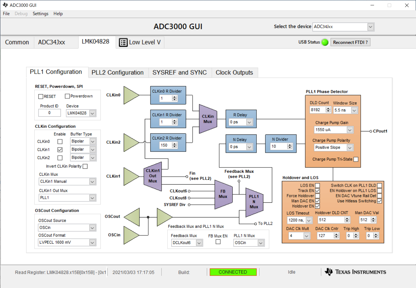
We have a problem that PLL1 of LMK04828 mounted on ADC34J45EVM does not lock by external clock (CLK1IN).

The external clock is a 10MHz sine wave.

LED D3(LMK LOCKED)  is not turning on.

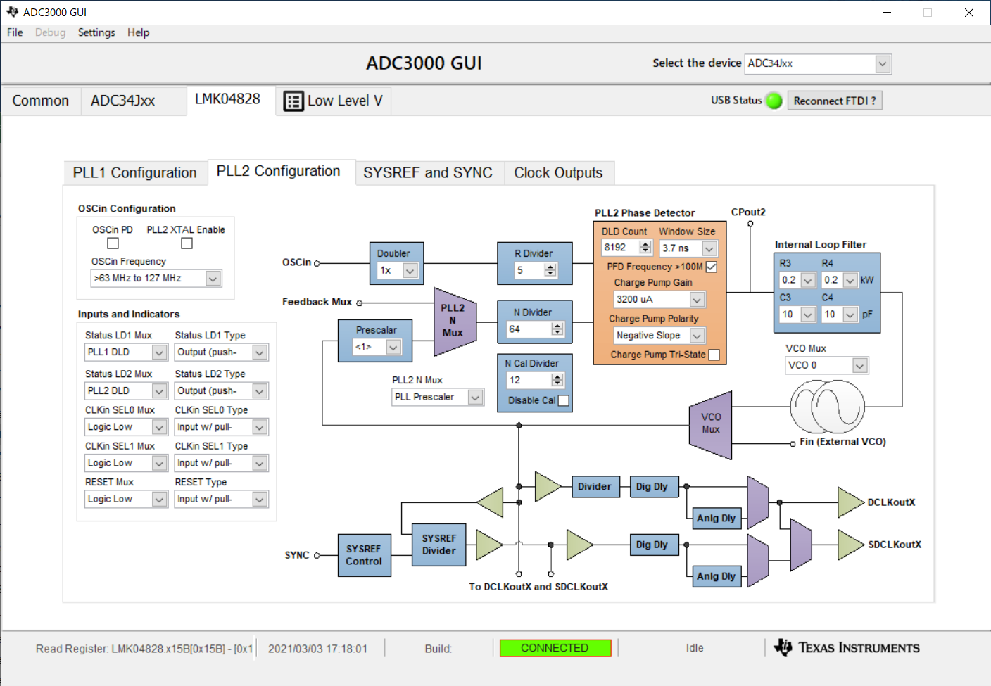
But, LED D4(PLL2 LOCKED) is turning on.

I've attached our ADC3000 GUI settings so can you tell me if there's anything wrong?

Regards.

  • Hi user5973786,

    Thanks for the post. I will check with a more experienced team member and get back to you.

    Regards, Chase

  • User,

    Make sure there is a shunt on JP6 and you see 100MHz at C92. On the GUI, in the PLL1 Configuration tab, disable "Use Hitless Switching" which is located in the burnt orange box. I notice with this enabled, sometimes it prevents PLL1 from locking. What is the amplitude of the 10MHz input on J10?

    Regards,

    Jim 

  • Hi jim,

    Thank you for your comment.JP6 is shunted. I saw 100MHz on C92.

    I disabled "Use Hitless Switching" but did not lock PLL1.

    The amplitude of the 10MHz input on J10 is 2Vpp. I set The amplitude of the 10MHz input on J10 to 3Vpp or 4Vpp, but the PLL1 did not lock.

    Can you tell me if the frequency or amplitude is wrong?

    Regards.

  • Hi,

    Please load the configuration file "ADC3xJxx_128MSPS_Operation_LMK_Setting", and then make the edits that you shared to the PLLs. I removed the jumper from JP6, and supplied a 100 MHz sinewave (+10 dBm) to J10. I also tried with a 10 MHz sinewave input, and it worked as well.

    While I did not get the PLL1 LED to turn on (lock), I did get valid data capture on the TSW14J56EVM. Additionally, please ensure that the LMK clock divider "CLKout 2 and CLK3" are set to "10", not "20".

    What is the expected sampling frequency?

    Best Regards,

    Dan

  • Hi Dan,

    Thank you for your comment.

    Sampling frequency is 128MHz. Did you lock PLL1 in your settings?

    Regards.

  • Hi,

    I just wanted you to know that we will verify operation at your sampling frequency in the upcoming days. Will keep you posted!

    Regards, Chase

  • Hi,

    I have verified everything runs fine at 128MHz this afternoon. Similar to Dan's comment above, LED D3 did not turn on in my experience either...

    Thanks, Chase

  • Hi Chase,

    Thank you for reporting your results. 

    Is Phase detector of PLL1 not work because LED D3 did not turn on?  What settings should I set on the LMK04828 for Phase detector of PLL1 to work?

    Regards,

  • Hi,

    I would like to suggest increasing the window size from 5.5ns to 18.6ns or 40ns to see if this lets PLL1 lock

    Thanks

  • Hi Chase,

    Thank you for your comment. I tried changing the window size and LED D3 turned on a little. In this state, I set "Status LD1 MUX" to "PLL1_N/2" and "Status LD2 MUX" to "PLL1_R/2". When I saw "PLL1_N/2" and "PLL1_R/2" on an oscilloscope, they were asynchronous. Does this result indicate that PLL1 is unlocked?

    Regards,

  • Hi,

    I believe the reason it's not as bright as the other status LEDs is it's not constantly on due to locking and resetting. If you decrease the required lock count register, PLL1_DLD_CNT at address 0x15C, does the LED come on brighter (since it will lock more frequently)?

    Thanks, Chase

  • Hi,

    I decrease the lock count register(PLL1_DLD_CNT), and the LED became brighter. But again I saw "PLL1_N/2" and "PLL1_R/2" on the oscilloscope, they were asynchronous. Is this a problem?

    Can you tell me the proper PLL1_DLD_CNT and PLL1_WND_SIZE settings?

    Regards,

  • Hi all,

    The slew rate of a 10MHz sine wave clock is bad, this could be one of the reasons why PLL1 did not lock. Increasing the voltage swing can improve slew rate but 4V seems to be violating the electrical spec. If possible, use 10MHz square wave clock. To debug, we can use 100MHz sine wave clock, but set CLKin1 divider to 10 to maintain the same fpd. 

    PLL1 fpd is 10MHz, so I think the lock detect window size may not help too much. To debug, I agree to make window size bigger and DLD count smaller.

    PLL1 fpd is 10MHz while the charge pump current is 1.55mA, what is the intended loop bandwidth? What are the loop filter component values?

  • Hi Noel Fung,

    I tried using 10MHz square wave clock but PLL1 did not lock. Now I don't have a device that can output 100MHz clock, so I can't try using 100MHz clock.

     I haven't changed the loop filter component from the default state of  "ADC34J45EVM". So, if the loop filter component is the same as the schematic(ADC34JXXEVM-SCH_C.pdf), C1 is 0.1uF, R2 is 39k ohms and C2 is 0.68uF. 

    I don't know the proper loop bandwidth value. So can you tell me the proper loop bandwidth value

    Regards,

  • Hi There,

    I just downloaded the schematic, and found there is a transformer after J10. Could you check what is the 10MHz clock waveform looks like at C71? If possible, share the waveform here.

    What is the voltage at pin 1 of Y1? Isn't it 3.3V? Can you remove R40 and try again?

  • Hi Noel Fung,

    I checked the 10MHz clock waveform at C71. The amplitude of the 10MHz clock was 980mVp-p.

    The voltage at pin 1 of Y1 is 3.3V.  I removed R40. The voltage at pin 1 of Y1 became 0V and PLL1 locked. What is the intention of mounting the R40?

    Regards,

  • Hi There,

    Is the 10MHz waveform a square wave or clipped-sine wave?

    The voltage should not be 0V, it should be around 1.65V when PLL1 is locked. 

    in a normal PLL configuration, R40 is not needed, PLL1 will provide the charge pump current to lock the VCXO. I don't know how this EVM is design, maybe this resistor is reserved for some specific use.

  • Hi Noel Fung,

    I’m sorry for the late reply. The 10MHz waveform is a unclipped-sine wave.

    I checked the voltage at pin 1 of Y1 again. The voltage is 1.68V.

    I realized that R20 is not needed.

    Regards,

  • Hi There,

    1.68V is a reasonable voltage. Glad that the problem is resolved.