This thread has been locked.

If you have a related question, please click the "Ask a related question" button in the top right corner. The newly created question will be automatically linked to this question.

ADS124S06: Spikes on data

Part Number: ADS124S06
Other Parts Discussed in Thread: ADS1248

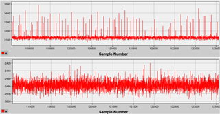
Hi, I still have a problem with my ADC. Spikes are on every configuration of Measuring Bridge, parallel and series.

configuration:

static uint8_t m_tx_buf_CONF_1[]    = {(WREG|INPMUX), 0x03, (MUX_P_AIN1|MUX_N_AIN0), (DELAY_64|PGA_ON|GAIN_128), (G_CHOP_ON|CLK_INT|MODE_SS|FILTER_LL|SPS_2000), (REFP_BUF_EN|REFN_BUF_EN|REF_0|INT_REF_ON_WHEN_CONV)};
static uint8_t m_tx_buf_CONF_2[]    = {(WREG|INPMUX), 0x03, (MUX_P_AIN3|MUX_N_AIN2), (DELAY_64|PGA_ON|GAIN_128), (G_CHOP_ON|CLK_INT|MODE_SS|FILTER_LL|SPS_2000), (REFP_BUF_EN|REFN_BUF_DIS|REF_0|INT_REF_ON_WHEN_CONV)};
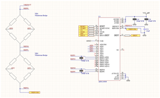
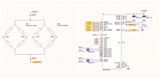
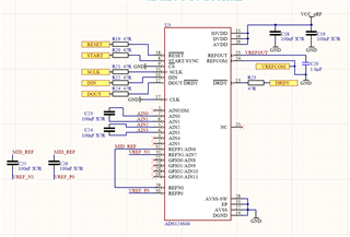
My design:

And also the data from converter:

  • Hi Marcin,

    One thing I notice is that you are missing the required 330nF capacitor between AVDD and AVSS.  This is discussed in the ADS124S06 datasheet in section 11.4.

    As far as troubleshooting, first of all I would look at your expectations to see if your expectations can be met based on ADC noise from quantization. Second, you are attempting a number of actions that I cannot fully understand, such as timing between conversions.  I would attempt to discover the source of the spikes by simplifying as much as possible what is going on to see if the problem might be external noise and/or aliasing or possibly caused by analog settling.

    • Use continuous mode instead of single-shot.  This will help to determine if there is more consistency in the measurements and if any additional delay may be required in the start of conversion.
    • Turn off global chop.  What does the data look like without global chop?  As bridge devices will have some form of resistance, any analog settling must be accounted for in the chopping.  You may need to extend the delay time when using global chop.
    • When using a lower data rate, do you see a significant improvement?  There may be external noise that may be filtered more effectively with the digital filter, such as power line-cycle noise.
    • If the reference input is at or near the AVDD supply voltage, you may want to disable the positive reference buffer.

    These are some of the things I would look into and primarily into settling delays especially when using global chop.  Achieving a low-noise, precision result is not a simple process.  It takes a great deal of effort in design and implementation.

    Best regards,

    Bob B

  • Hi Bob,
    Thank you for your patencie In this topic. I will try to figure out my case once again.
    I have 2 Wheatstone Bridges (Strain Gauges 1kOhm In full-bridge configuration). Expected data rate  is 2000SPS. The measuremenets should be muliplexed/alternating.
    The device is powered from LiPo battery so the low power solutions are desirable. ADS is supplied from LDO 3.1V.
    So the first conception is Wheatstone bridge connected in series and use both pair of external  REF inputs. The whole system supplied from VREFOUT (with configuration: INT_REF_ON_WHEN_CONV).

    Slowing the data rate do not help to avoid peaks, it still ocure but in different frequency. Slowing the data rate lower noise as per specification only.

    I would like to add that I am seeing similar sampling results in ADS1248 in an identical configuration. The difference is that ADS1248 is powered directly from coin 3V battery.

    Sampling way is identical like in ADS124S06 but with appropriate register configuration.

    Summarizing: I have tried different register configuration with not satisfying results. In most cases AIN0 and AIN2 were more susceptible for peaks. I tried to change REF inputs only for AIN0 and AIN2 to REF1 and REF_INTERNAL without better performance. I am afraid that is some noise from power line or RF from uC with 2.4GHz interface, but I don't know what way they can get to the converter.

    Best regards

    Marcin

  • Hi Marcin,

    I don't see any analog filtering to the inputs.  You should have at least some differential capacitors across the inputs.  

    Bottom line is you need to discover the source of the noise before you can resolve the noise issue.  As I mentioned in my last post, I would simplify this as much as possible.  Use a DC power source from a lab supply or something where you don't need to worry about the voltage/current.  Collect data continuously for a single input channel and run the data through an FFT to see if there is a particular frequency or set of frequencies that are causing you issues.

    How are you determining that the noise peaks are worse on AIN0 and AIN2?

    Best regards,

    Bob B