This thread has been locked.

If you have a related question, please click the "Ask a related question" button in the top right corner. The newly created question will be automatically linked to this question.

ADC with RAM buffer

Other Parts Discussed in Thread: INA333, INA818, INA293

Hi -

I'm looking for an ADC that can be triggered to start capturing samples and buffering those samples into a local memory for retrieval via SPI or I2C after completion.

For example, on a single channel via a trigger I would like to capture samples for ~34 ms at a rate of 200 kS/s with all of those samples buffered.  This would happen in parallel across multiple discrete ADCs in a similar configuration.

More specifics:

  • Number of channels:  >= 1
  • Sample rate:  >= 200 kS/s
  • Input voltage level: 0 to 3.3V (or 5V okay too) single-ended
  • Buffer size:  8k RAM
  • Digital Interface:  I2C or SPI
  • ADC Bits:  >= 10 bits 
  • Trigger source:  Ideally GPIO that could start trigger on discrete parallel ADCs

Ideally, the device would be configurable and essentially be an ADC with a back-end RAM buffer.  But, if this is not available, does TI offer an integrated solution which would include a processor, ADC, RAM, and could function as either in I2C or Slave device?  ...or does TI has an alternate solution?

Thanks in advance,

Tom

  • Hi Tom,

    I believe this part could meet your requirements:

    https://www.ti.com/product/MSP430FR2422

    The FRAM in this device can also be used to buffer ADC data.

    BR,
    Leo

  • Thanks for the response Leo.  

    I do think the ADC will work nicely for my application in the MSP430FR422.

    One follow-up question, can you recommend a TI current sense amp and instrumentation amp for this SAR ADC?

    I am measuring power supply currents and voltages in the range of 0 to 1.0V and 0 to 500 mA.  There will be a 40 mΩ shunt resistor for the high-side unidirectional current sense amp and ~40 mV full scale range.  

    The current sense amp I was planning on using is the TI INA240A2 since it has ~400kHz bandwidth.

    Is this current sense amp compatible with the MSP430FR422 SAR ADC?

    Could you please recommend a TI amplifier to convert the 0 to 1.0V to the full scale range of the SAR ADC?

    Thanks again!

    Tom

  • Hi Tom,

    Another option might be to consider one of our micro-controllers with integrated opamps such as:

    https://www.ti.com/product/MSP430FR2311

    The family reference guide(for both FR24x and FR23x device families) describes the ADC operation which supports internal 1.5V reference or an external reference:

    https://www.ti.com/lit/ug/slau445i/slau445i.pdf

    BR,

    Leo

  • Hi Leo -

    Thanks for that input.  However, it seems that these families of parts either go down in available FRAM (<=4 kB) or I have to jump up to 16 kB/32kB and 32 GPIO pins with added cost.  

    Since I need current sense amps as well as voltage measurement (instrumentation?) amps, and may choose to wire these up to multiple A/D channels, it seems having the flexibility of a discrete external amplifier solution would be preferable.

    Can you recommend the appropriate TI amplifiers for this purpose?

    Thanks, 

    Tom

  • Hi Tom,

    I'm going to transfer this thread to the analog forum to better address your analog specific needs - if you have any additional questions on the digital side, please feel free to make another post on this forum.

    BR,

    Leo

  • Hi  Tom,

    Enclosing is a link about Instrumentation amplifier selection. 

    https://e2e.ti.com/support/amplifiers/f/amplifiers-forum/818894/faq-how-do-instrumentation-amplifiers-inas-fit-into-my-design

    If you are able to provide us about your current sensing measurement requirements, we can help you in details. Please provide us the following current sensing information.

    1. high side or low side of current sensing.

    2. DC common mode bus voltage, sensing resistor value and sensing current level (AC or DC).

    3. BW, Gain and IA's power rail requirements

    If you have any questions, please let us know. 

    Best,

    Raymond

  • Hi Raymond -

    Thanks for your response.  The answers to your questions:

    1.  My application is a high-side current sense.  (I am sensing 4 different power supplies into our SoC)

    2.  The DC common bus mode voltages for the 4 supplies (~0.65V, 0.8V,  1.8V, 3.3V).  The sensing resistor for each of them is 40 mΩ and the range of the voltage is expected to be ~40 mV.

    3.  I will be sampling at the maximum rate of the ADC (200 kS/s).  I'd like bandwidth that supports this.  For gain, I'd like each supply to efficiently use the 3.3V range of the ADC.  (0.65V and 0.8V: Gain 3x), (1.8V and 3.3V perhaps gain is just 1).

    Thanks in advance,

    Tom

  • Hi Tom,

    Thanks for providing the design requirements.

    I still have several additional questions.

    The application looks like a low voltage, low current and higher BW high side current sensing application. What are current accuracy do you expect to obtained from the application? Instrumentation amplifiers (IAs) will give you the very accurate I-V measurement, but the costs will be also higher in general, especially you will need 4 of IAs as you stated. 

    It is likely that the positive and negative power supplies are regulated from a higher voltage supplying rails. Is it acceptable to measure the output current from the higher voltage regulator? Or you'd like to measure the current from sub-power supply rails. What voltage rails will the current measurement op amps be powered from, +5Vdc,  dual supply voltage rails or others?

    BTW, are these LDO regulators. I am curious why you are sampling the current information so high, unless it is switching inductor's current. What are maximum current of each supply rails?

    Here is another option. 

    Use a current shunt monitor (some has build-in shunt resistor + current sensing amplifier). So it will be more compact in current sensing design. The current monitor IC product is supported by our CSM/CSA team. 

    Please let us know how you want to proceed with the application. 

    Best,

    Raymond 

  • Hi Raymond -

    Please see responses below.

    The application looks like a low voltage, low current and higher BW high side current sensing application. What are current accuracy do you expect to obtained from the application?

    • For the shunt resistor voltage, I'm hoping for something 1 µV or less resolution. 

    It is likely that the positive and negative power supplies are regulated from a higher voltage supplying rails. Is it acceptable to measure the output current from the higher voltage regulator? Or you'd like to measure the current from sub-power supply rails. What voltage rails will the current measurement op amps be powered from, +5Vdc,  dual supply voltage rails or others?

    • I need each supply's individual power to be measured into our SoC.  I cannot simply measure the upstream regulator as I need the individual component power measurement from each supply rail.

    BTW, are these LDO regulators. I am curious why you are sampling the current information so high, unless it is switching inductor's current. What are maximum current of each supply rails?

    • The reason I need high resolution is that the SoC that is running will be mostly drawing very low power, but have very brief bursts of dynamic activity.  I'm trying to capture a clear picture of the shape of this short burst.  

    Thanks,

    Tom

  • Hi Tom,

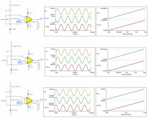
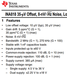
    Ok, I did several high side current sensing simulation with INA818 instrumentation amplifier (IA) INA333 will work for low voltage application as well. This is not finalized simulation, since I made many assumptions. Once you provide me with more detailed measurement requirements, I can modify the simulations per your requirements.  

    Below are some of my comments.

    1. you may use single supply rail for the IA high side application. You may also use asymmetric power rails, say Vee=-0.65Vdc with Vcc=5V or higher. 

    2. INA818 is one of lowest Voffset(Vos) IA we have. So INA818 will have slight dc offset, but it will not result any problems to measure 1uV in delta signal across 40mOhm Rsense shunt. Since you are using MCU, you can "zero" out  the measured Vos prior to the current measurement. Once the Vos DC offset is subtracted or removed, I to V conversion is a linear relationship (I=0, Vout=0 relationship), see the graphs below. 

    3. You may increase gains of IA to maximize your ADC resolutions. Vout signal is very small, unless you have huge current. Also, you can increase the Rshunt value. If the Isense current is low, I^2R loss will be minimum. 

    4. If the monitored power regulators have high transient events or high inrush currents, please let me know these parameters. We may need to protect IAs. If your load is complex in nature, please let me know well. 

    Enclosed are simulations for the above plots. Please let me know if you have additional questions. 

    INA818 high side Isense -0.65Vcc 03172021.TSC

    INA818 high side Isense 0.8Vcc 03172021.TSC

    INA818 high side Isense 3.3Vcc 03172021.TSC

    Best,

    Raymond

  • Hi Raymond -

    Thanks very much for taking the time to run these simulations and make these recommendations.  It helps me to understand the constraints of the design.  I will review your points further.  One thing to note is that I cannot change the value of the shunt resistor as it is fixed by other design considerations.

    In a separate thread with the IA forum, it was recommended to me that the IA have at least 4x the bandwidth of the sample rate of the ADC.  Since I'm sampling at 200 kS/s, that would imply that I need the IA to have a bandwidth of 800 kHz or more.  For that reason, it was recommended that I use an INA293.  Though the gains are not as flexible as the INA818 (which is set by a resistor), the bandwidth is 1000 kHz or more.  Since I would consider the ideal maximum IR drop to be 40 mV for all of these measurements, the INA293A3 with a gain of 100 seems like it would come close to maximizing the full scale range.  (I actually expect the maximum IR drop across the shunt to be ~30 mV but am padding a bit at the top).

    Do you see any concerns with the INA293?

    Thanks again!

    Tom

  • Hi Tom,

    INA293 is current sense monitor and it is not supported by our team. However, I did recommend the particular approach earlier. 

    If you are using low gain application (say Gain=10 or higher), INA818 will have plenty oversampling BW for the application .Yes, if you want to see 200kHz current transient events, you will need to oversample the events with ADC at 6X range (800ksps -1.2MSPS). Since you are only sampling 200kHz via ADC, you are looking at 40kHz-50Hz current changing activities. And INA818 has the plenty BW to support the data acquisition, and it is more precise method to measure small current levels. 

    If you want to use INA293, I can transfer you to the supporting team. Also, INA293 will be lower in cost, which I have informed earlier.

    Please let me know which route you are going to take. My objectives are to provide you with the best support and inform you the pros and cons in each product and/or design approach. 

    Best,

    Raymond