This thread has been locked.

If you have a related question, please click the "Ask a related question" button in the top right corner. The newly created question will be automatically linked to this question.

ADS8363 driver settling

Other Parts Discussed in Thread: ADS8363, OPA2365, OPA365

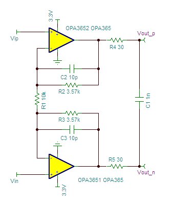
I would like to use ADS8363 fully differential driver configuration as reported in ADS8363 data sheet page 39 with following values:

C 1nF as suggest on data sheet

R = 4 Ohm as calculated using (6), n=16, tacq =100 ns

R1 between OPA2365 output and  non inverting input 3570 Ohm

R2 between the two OPA2365 non inverting input 10 KOhm to have a 1.7 amplification value.

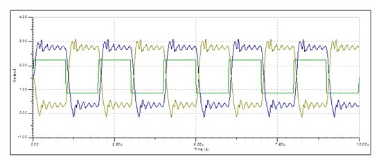
Simulating with spice (OPA365 model from TI) and applying a differential 2 MHz square signal duty cycle 50 % (rise and fall 10 ns),

circuit output present an oscillation that could corrupt ADC read value.

Is this behaviour real ?

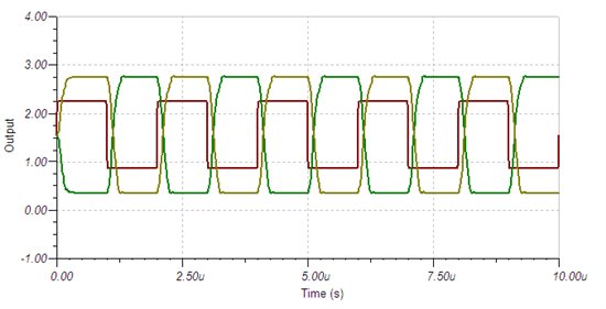
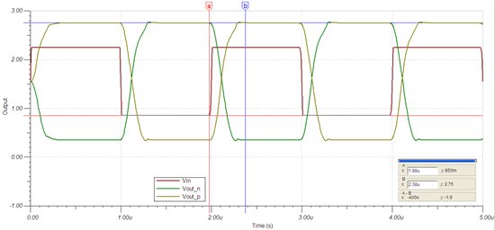
Do I need a stabilization trick like a feed back capacitor (10/20 pF) ?


Thank you in advance,

Daniele.


  • Hi Daniele,

    I have a couple questions for you.  The ADS8363 converts at a maximum speed of 1MSPs, as this is a Nyquist converter, why are you applying a 2MHz signal into the OPA2365?  Can you share the schematic of your simulation?  The resistors in the datasheet are feeding into the inverting inputs.  I'd like to try and re-create your simulation results.

  • Hi Tom,

    there were typing errors in my post:

    signal frequency is 500 kHz (period 2 us) and not 2 MHz

    resistor are feeding into inverting inputs and not non inverting.

    In the attached file you find simulation schematic, result plot and netlist.

    Thank you very  much,

    Daniele.

    2273.ads8363_driver.doc

  • Hi Daniele,

    I simulated your circuit in TINA-TI and I was able to replicate your results (see below). I think you can expect to see these results on the bench.

    There are some modifications you can make to the circuit to improve the settling time and overshoot. In my simulation I incresed the value of the isolation resistors (R4 and R5 below) to 30 Ohms and I added a feedback cap of 10 pF, as you correctly suspected. This resulted in the following waveforms:

    One thing that is worth noting is that there is a driver delay between an input change to output settling of about 400ns (shown in the following graph). If this delay is too long for your application then a faster driver with more bandwidth should be used.