Hi team,
1. set the sampling rate to 250sps, continuous conversion mode
2. Configure ADS1115 Lo_thresh to the maximum value of 0x7FFF and Hi_thresh to the minimum value of 0x8000
3. After the conversion, the RDY pin generates an interrupt, and then reads the conversion data through I2C.
The problem is: when SPS is 250, the output frequency of RDY pin (Pin2) is not equal to 250Hz, which is about 205hz. Other sampling frequencies are tested. Similarly, the output frequency of RDY pin is not equal to the set SPS. What's the problem?
The output waveform of RDY pin measured by oscilloscope is as follows:

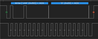
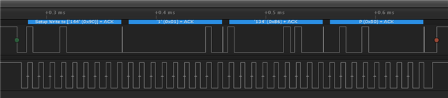
Ads1115 is configured as follows:
1, set the low thread register (2H) value to 0x7F, 0xff (0x7FFF)
2. Set the value of hi thread register (3H) to 0x80, 0x00 (0x8000)

3. Set the value of config register (1H) to 0x86, and then start the continuous conversion

4, point the register to conversion register (0h)