This thread has been locked.

If you have a related question, please click the "Ask a related question" button in the top right corner. The newly created question will be automatically linked to this question.

ADC128D818: OFFSET ERRORS EXCEEDING DATASHEET LIMITS

Part Number: ADC128D818
Other Parts Discussed in Thread: ADS7128, OPA320

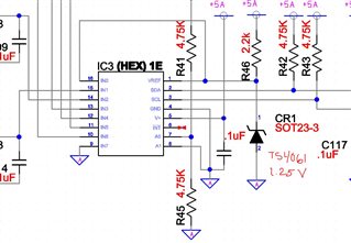
We are using ADC128D818 in continuous Mode with the internal 2.56V Reference, with the ADC powered from 5V.

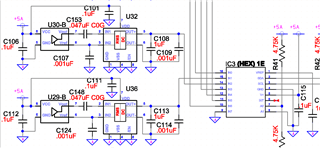
In our example circuit, we are reading single ended values which are output from an LTC1966 RMS to DC converter, which has an output impedance of approximately 30k and whos output is buffered by a 1uF ceramic cap, and a 1nF Ceramic filter cap at the pins of ADC128D818.

Our expected analog voltage ranges from this circuit are between 100mV and 1.00V.

When we read back the raw ADC counts, we are consistently low by about 8 counts over the entire 100mV to 1.00V input range.

At first we expected that the ADC may be slightly loading the 30kohm Impecance of the RMS to DC converter, however, measurement with a 6digit DMM confirms that voltages at the ADC are as expected while the reported value is low by approximately 8 counts.  

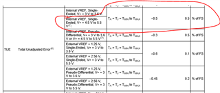
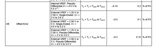
The 8bit offset is within the Total Unadjusted Error for this ADC, but seems to fall outside of the ~6bit error range for offset.

We have approximately 5 samples of the circuit constructed, with all samples showing a consistent error of about 6 bits low.

We will attempt to buffer the output of the LTC1966 to get a lower impedance output, but do not feel that this is the root of the issue.

Are there other things that we should explore? Or is this simply within the expected error of the ADC.

  • For what it's worth, we added an op-amp buffer between the LTC1966 and the ADC to eliminate concerns about output impedance.  The results are unchanged, and all converted errors in the range of interest are consistently 6-8 bits low. 

  • Hello Alex,

    I'm looking into this, and I'll get back to you by Wednesday with some more information. Is there any chance that the V+ is drooping at all? The offset error can change a bit with temperature or V+, although I would not expect it to have an effect of the size that you are seeing.

    Also, as a side note, you may be interested in the ADS7128 for applications like this one. It includes an internal RMS module instead of needing to use an external RMS to DC converter.

    Regards,

  • Alex,

    I am helping Scott.  I have a few questions / comments.

    1. The offset is specified in several different ways depending on the mode of operation.  For internal Vref it is specified: offset = 2^12 x 0.2/100 = 8 codes.  Can you confirm the mode of operation you are using?  Note: for most devices you see that measured results are in line with the typical spec and very few approach the maximum. Unfortunately,  this device doesn’t have a typical.  Nevertheless, I would expect that the typical offset should be better than the max.  I suspect some other factor (e.g. the driver) is impacting this measurement.
    2. Your schematic shows some inputs going off the page.  Do these inputs also go to other LTC1966?  The reason for the question is that I want to understand if all the channels show this offset, or if only the channels using the LTC1966 show the offset.  Is the LTC introducing additional offset?
    3. Do all the channels show the same offset?
    4. You mentioned that the offset looks consistent for inputs from 100mV to 1V.  Can you confirm how consistent?  The real question here is to confirm that we are not looking at a combination of offset and gain error.  Can you plot the error?
    5. Did you account for the reference error?  This will introduce a gain error.
    6. Are you measuring the ADC input directly at the ADC input?  Is the GND lead on the ADS7128 GND?
    7. Can you disconnect an input from the LTC1966 and connect it to GND or a precision test signal. 
    8. Sometimes slow amplifiers will cause setting issues.  That is, when the ADC samples the input signal, the voltage on the filter capacitor (1uF in your example) droops.  If the amplifier is fast enough, the amplifier will replenish the charge and correct the droop by the end of the acquisition cycle.  You mentioned using a buffer.  This would be a good experiment to make sure that bandwidth / sampling rate is not an issue.  Please choose a fast low error amplifier (i.e. OPA320 is our go-to for SAR converters).  Note: this probably shouldn’t be needed but I would like to eliminate the settling as a possibility.  Also, note that settling errors typically will not show up as a constant offset, so I don’t’ think this is a settling error.  Nevertheless, this is always a good thing to double check when driving a SAR.
    1. The offset is specified in several different ways depending on the mode of operation.  For internal Vref it is specified: offset = 2^12 x 0.2/100 = 8 codes.  Can you confirm the mode of operation you are using?  Note: for most devices you see that measured results are in line with the typical spec and very few approach the maximum. Unfortunately,  this device doesn’t have a typical.  Nevertheless, I would expect that the typical offset should be better than the max.  I suspect some other factor (e.g. the driver) is impacting this measurement. We expected this as well, but Buffering the signal with a couple of different low error high speed opamps shows no impact in the error.
    2. Your schematic shows some inputs going off the page.  Do these inputs also go to other LTC1966?  The reason for the question is that I want to understand if all the channels show this offset, or if only the channels using the LTC1966 show the offset.  Is the LTC introducing additional offset?  The offset is consistent across all channels of the ADC.  These are all interfaced to LTC1966s.  
    3. Do all the channels show the same offset?  Within our reasonable ability to measure w/ a 6digit DMM and compare against the nominally given internal reference, the error is consistent across channels.  
    4. You mentioned that the offset looks consistent for inputs from 100mV to 1V.  Can you confirm how consistent?  The real question here is to confirm that we are not looking at a combination of offset and gain error.  Can you plot the error?  It is consistently 6-8 bits over this entire range from 100mV to 1V.
    5. Did you account for the reference error?  This will introduce a gain error. No tolerance on the reference is given in the datasheet, however a post from TI on e2e gives the pass/fail of the laser trimmed reference as 300uV.  Not enough to account for this shift
    6. Are you measuring the ADC input directly at the ADC input?  Is the GND lead on the ADS7128 GND?  Yes, the measurement is being taken from the .001uF filter cap to the ADC GND.
    7. Can you disconnect an input from the LTC1966 and connect it to GND or a precision test signal. We did one better, we connected a 1.25V precision reference diode to the external REFERENCE pin, and also connected this reference to channel one of the ADC. We then configured the ADC to use the external reference. The ADC Consistently converts either FF0 or FF1 for the channel directly tied to the reference pin, which is 15-16 bits low.  Seeming off by an awful lot.  A schematic of this setup is given below.
    8. Sometimes slow amplifiers will cause setting issues.  That is, when the ADC samples the input signal, the voltage on the filter capacitor (1uF in your example) droops.  If the amplifier is fast enough, the amplifier will replenish the charge and correct the droop by the end of the acquisition cycle.  You mentioned using a buffer.  This would be a good experiment to make sure that bandwidth / sampling rate is not an issue.  Please choose a fast low error amplifier (i.e. OPA320 is our go-to for SAR converters).  Note: this probably shouldn’t be needed but I would like to eliminate the settling as a possibility.  Also, note that settling errors typically will not show up as a constant offset, so I don’t’ think this is a settling error.  Nevertheless, this is always a good thing to double check when driving a SAR.  Worth considering.