This thread has been locked.

If you have a related question, please click the "Ask a related question" button in the top right corner. The newly created question will be automatically linked to this question.

AMC1336: Inquiry about Dout.

Part Number: AMC1336

Hi TI experts,
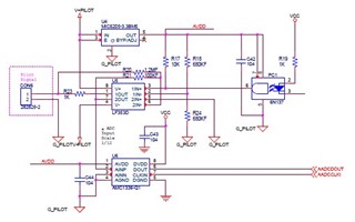
SCH

-1V, -0.75V, -0.5V, 0V are input to the AMC1336 input pin. However, Dout is not consistently output. 

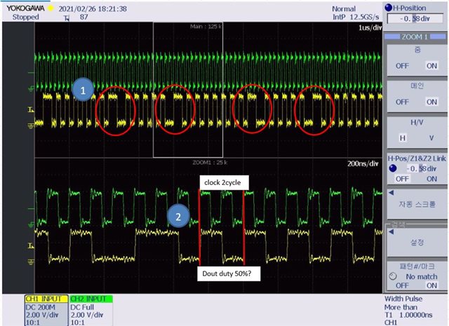
When 0V is input, Dout waveform is attached.
PILOT_M1V.zip

Dout output waveform of other input voltage is also attached.

For 0V input, the duty of Dout is 50%. Please review the reason why it is not output normally.

Thanks,

Downey Kim.

  • Hi Downey,

    Your plots for the output of the AMC1336 look correct to me, what were you expecting to see on the output of the modulator?  With 0Vin, you should see 50% ones and zeros.

  • Hi Hendrick,

    Is it correct to check the input voltage with the duty of Dout per clock 1 cycle?

    1. Look at the places marked in red. It is an irregular Dout. Is this normal?

    2. Should I check the Dout duty during 2 cycles of clock?

    (Green is clock. Yellow is Dout. )

    Please check it.

    Thanks.

  • Hi Downey,

    You should not be checking for duty cycle, the output is a bit-stream, not a PWM signal.  You should be looking at the density of ones and zeros.  For example, in the first red circle, you have 1011001 and the second is 1001101.  If you look at the entire string in the zoom portion, there are 9 'one's and 8 'zeros'.  If you expand that a little, you should see 50% ones and 50% zeros.

  • Hi Hendrick,

    Thanks for explaining!

    Should I check the 16bit value to read the voltage?

    The waveform below is Dout when 0.75V is input.

    Could you please explain how to analyze the Dout of the waveform below?

    Thanks for the help.

    Downey Kim.

  • Hi Downey,

    In general, the AMC1336 acts like the front end of any ordinary Delta-Sigma Analog to Digital Converter - the difference is the digital filtering becomes the responsibility of your processor or FPGA.  An ordinary DS ADC has a built in digital filter that accumulates the delta-sigma bit stream and then decimates the result giving you an output word that is read by an SPI or I2C peripheral on the controller.  They usually have a fixed filter order and oversampling rate (OSR) which dictates the precision of the conversion result. 

    With the DS Modulators, you need to provide the filter function, you determine what the filter order and OSR needs to be to match your performance criteria.  Here is an Excel Calculator that shows you some filter options.  Here is an Application Note that describes the operation of a Delta-Sigma ADC in more detail.  Think of the AMC1336 as the first block after the Analog Input as shown in Figure 1 of the application note.