This thread has been locked.

If you have a related question, please click the "Ask a related question" button in the top right corner. The newly created question will be automatically linked to this question.

ADS1248: software configurable RTD *or* TC inputs

Part Number: ADS1248


Hi all.

I'm developing a temperature sensor conditioning circuit (range 0°C to 350°C) for a custom industrial device. This device will acquire the temperature of two objects, and I need to allow free choice between RTDs or thermocouples as sensors. Specs are:

  • two temperature inputs;
  • RTD, PT100 type, two wire connection;
  • J or K thermocouples with cold junction compensation;
  • two inputs have the same sensors: two RTDs *or* two TC. No sensor type mixing allowed.
  • 4 readings per second for every input;

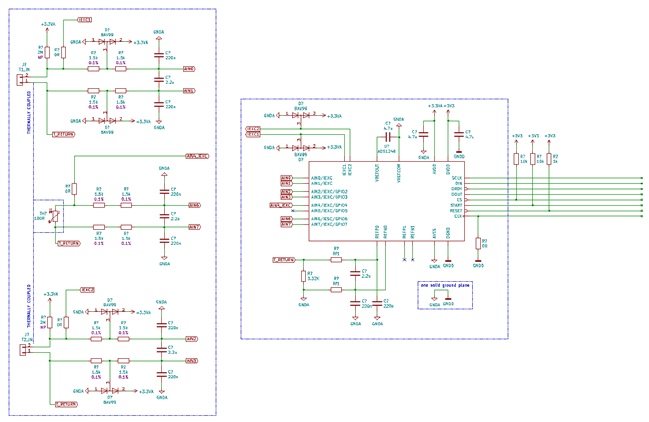
I'd like to avoid the use of external analog muxes, so I've come up with this solution ('NP' in schematics means 'Not Present'):

Questions are:

  1. Is there anything wrong/could it work?  
  2. in case of TC sensor:
    1. IEXCx can be activated to detect a burnout/disconnected sensor (instead of IBOR source and sink)? This should bypass the filtering resistor imbalances.
    2. Should I disconnect IEXCx mux *before* acquiring a new measure, or can I simply keep it on all the time?
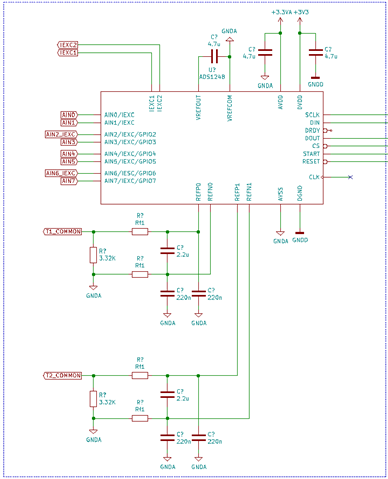
    3. REFPx/REFNx are here because they are needed for RTD operation. So they are not intended to perform a ratiometric measure. As per my understandings, REFPx will bias the TC junction common mode voltage to proper PGA/ADC operation (IEXC should be active?), and the 3.32K resistor between REFPx and REFNx becomes a dummy load for the voltage reference generator. Am I correct? Could this work properly?
    4. I'll use two spare adc inputs (for each sensor input) for two wire PTC measure (smd 0805 PT100 sensor, close and thermally coupled to the input block terminal), with ratiometric measure through REFPx/REFNx inputs. I should disconnect IEXCx from TC input, activate IEXC through internal mux, set the correct PGA gain and start a conversion. Is this ok?
  3.  In case of RTD sensors:
    1. is there any real point using REFP1/REFN1 and REFP2/REFN2 inputs, one for each RTD sensor? I feel that using them both gratifies my sense of symmetry, but it will cost more pcb room for RC filtering. What purpose REFP2/REFN2 inputs are intended for?
  4. Is there any reference design for dual sensor type (RTD or TC) input conditioning, without using external analog muxes?

This circuit section will be replicated many times in the same board with an fpga as a conductor, so I'm really trying to get it right first time!

Thank you in advance!

Cheers,

Eugenio.

  • Hi Eugenio,

    A couple of comments about this schematic

    • We generally do not recommend split ground planes, and instead recommend one solid ground plane where you connect both the analog and digital grounds. You can learn more about why this is the case here: https://e2e.ti.com/support/data-converters/f/data-converters-forum/755516/faq-pcb-layout-guidelines-and-grounding-recommendations-for-high-resolution-adcs
    • The cutoff frequency for your differential filter seems very low (I calculated about 12 Hz). If there is a step change on the input e.g. a wire break, it might take some time for the ADC to report back that this occurred. You might try reducing the size of the differential cap as well as the resistors.
    • You can tie both RTDs to the same common return point i.e. both to T1_COMMON or T2_COMMON, and remove the other reference resistor circuit.
    • The CLK pin appears to be unconnected, you either need to provide a clock source to the ADC or tie this pin to DGND to activate the internal oscillator
    • You might consider changing the 0ohm resistor on IEXC1 and IEXC2 to an actual value, as this will limit any current into these pins on the ADS1248 in case of an overvoltage event. You have the analog inputs protected with TVS diodes and current limiting resistors (as part of the filter), but nothing to protect the IEXCx pins from the outside world
    • It was not clear to me how you intended to bias the PTC (I think this should be RTD, not PTC, since you said it is a Pt100). For temp sensor input #1, if you run the current through AIN2/IEXC and try to measure with this same channel, then you are also seeing the voltage drop on the two filter resistors in your measurement. In other words, you have an additional 3kohm of resistance in the IDAC path that will be measured by AIN2. If the input terminals are thermally connected, or the RTD can be thermally connected to both, you might be able to use one RTD for CJC instead of two. This frees up two analog inputs, one of which could be used to excite the RTD similar to the main measurement channel (connected after the filter resistors)
    • Without knowing your specific application settings, keep in mind the IDAC compliance voltage. This is plotted in Figure 41 and 42 in the ADS1248 datasheet (note that AVDD = 5V in these plots, not 3.3V). The IDAC current begins to droop if the voltage at the IDAC pin is too close to AVDD, so this limits the amount of resistance you can have in the IDAC path (or the IDAC current magnitude that you can use)

    -Bryan

  • Bryan, thank your for your support!

    In the attached image there should be all your design updates. You're right about the onboard cold junction compensation: it will be an smd PT100 sensor, and it's possibile to arrange things to use just one of it. Neat!

    Now I know that I have to ready carefully the IDAC voltage compliance specs, and choose the right resistors (or even increase the analog voltage to +5V). The digital connections are not showed, but they'll go straight to fpga pins (with series resistor to smoothen up things, as suggested). In the schematics there resistors are still 0R, but they'll have valid values.

    Analog filter is quite 'hard': I'll run some tests to measure and fit to actual noise (still unknown). 

    Let me know If you think that I'm on the right direction!

    Cheers,

    Eugenio.

  • There is one reference design in TI's pdf. I don't remember which IC pdf they have mentioned but its too good and have designed temperature scanner with multiple input using that pdf. They have mentioned almost all the components and their values.

  • Hi Eugenio,

    This looks better now. There are some things that still need to be addressed as you mentioned (IDAC compliance, filter cutoff, etc.) but you have addressed several of the comments from my last post.

    Since you have the thermocouples tied to T_RETURN, when you excite the integrated RTD for CJC this will bias the thermocouples as well (bias voltage = IDAC current * 3.3k reference resistor). Therefore choose the IDAC current carefully as you generally want the bias point to be mid supply e.g. (AVDD-AVSS) / 2.

    I will also point out that you will need to switch between the thermocouple and CJC measurements since this is not a simultaneously sampling ADC, and also change the reference source each time (TC = internal VREF, CJC = REFx0). I think you are aware of this, but just wanted to point it out.

    -Bryan

  • I didn't quite get the issue about bias voltage on TC when measuring cold junction compensation RTD.

    Consider this case: the ads1248 has just acquired a TC value from input AIN1&AIN2, and next in the list is the RTD for CJC. I'm figuring out these steps:  

    1. disconnect IDAC from thermocouple, disabling IEXC1 output pin;
    2. disconnect PGA from AIN1&AIN2 (via internal MUX);
    3. connect IDAC to RTD (via internal MUX) through AIN4;
    4. change IDAC value to properly bias the PGA inputs;
    5. connect PGA to AIN6&AIN7 (via internal MUX);
    6. wait for everything to settle down, and perform an acquisition.

    Is this ok?

  • Hi Eugenio,

    How are you planning to bias the TCs? Since a TC is self-powered, it needs a bias voltage to make sure the TC voltage is within the input range of the ADC that is measuring it. Running a current through the TC via IEXC would likely create additional voltage drops that would interfere with the TC measurement. Usually the bias voltage is established via pull up/pull-down resistors (e.g. the 2Mohm resistor you have in your circuit) or using the internal VBIAS feature on the ADC. There are other methods as well, so I wanted to understand how you were accomplishing this?

    Your CJC measurement routine looks okay. I would also make sure to change the VREF source, as the TC measurement would use the ADC's internal VREF while the RTD measurements (both the external RTDs and the CJC RTD) use REFx0.

    -Bryan

  • Whoops, you're right: this will add big error voltage caused by TC's wires. Albeit being relatively short (tens of cm), those wires are not made of copper, so higher resistance should be expected. In case of J type TC (iron+costantan), this totale stray resistance is in the range of 70mOhm/cm (thumb measure). Quite a lot, actually!

    So the 2Megs biasing resistor needs to be present in the board. In case of RTD this will add an extra (smallish) current, but should not be an issue, because of ratiometric measure. Is this correct?

    Other option: could I use AIN5 (left unconnected in my schematic), muxed internally with an IDAC current generator (not used during TC measure), and connected straight to T_RETURN node? If Idac=500uA this should bias the T_RETURN voltage, and so the TC inputs. Could this work?

  • Hi Eugenio,

    I would only recommend the PU/PD resistors if you can switch them in and out of the measurement path. These will absolutely interfere with the RTD measurements if they are constantly connected to the circuit. The benefit of using PU/PD resistors is that they offer continuous open wire detection. However, if your leads are very short perhaps this would not be an issue.

    Your option of using AIN5 to bias the TCs should work, alternatively you could just use AIN4 since it is already connected (through the CJC RTD) to T_RETURN. You would just have to consider that the current flows through the CJC RTD as well as the reference resistor.

    But if you have no other use for AIN5 then that would likely be the best option, and I agree that the 500uA will bias the TCs right to mid-supply.

    Let me know if you have any other questions.

    -Bryan

  • Brian, your help has been precise and time saving!

    I'll try to bake out a small test board to verify the overall design.

    Cheers,

    Eugenio.

  • Sounds good Eugenio.

    If you have any additional questions, please start a new thread and we will answer them there. I will close this one for now.

    -Bryan