This thread has been locked.

If you have a related question, please click the "Ask a related question" button in the top right corner. The newly created question will be automatically linked to this question.

INTB not de-asserting

Part Number: LDC1612
Other Parts Discussed in Thread: MSP430FR5739

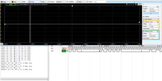
INTB will not de-assert(it's always logic low) which prevents the microprocessor from reading of data from DATA0_MSB and DATA0_LSB.   We've checked the microprocessor code and if we disconnect the INTB pin and we trigger the input INTB is connected to with a push button  the code executes correctly and the interrupt is called and the DATA0_ MSB and DATA0_LSB are read, this leads us to believe we've done something wrong with the LDC config but it seems straight forward.

We've hooked a scope up to the INTB pin and triggered reading of DATA0_MSB and then DATA0_LSB  and INTB didn't change state.    We've also tried reading the Status register 0x18 to see if that would cause INTB to de-assert it didn't.  The value in 0x18 is 0x48   which according to the data sheet is the Data Ready Flag and the Channel0 Unread Conversion, which seems correct.

The LDC registers are set up with the following write commands from the microprocessor in the order below

Register Address Value
CONFIG 0x1A 0x30C1
RCOUNT0 0x08 0x0A7C
OFFSET0 0x0C 0x0000
SETTLECOUNT0 0x10 0x5Fhe
CLOCK_DIVIDER0 0x14 0x1001
ERROR_CONFIG 0x19 0x0001
MUX_CONFIG 0x1B 0x0209
DRIVE_CURRENT0 0x1E 0xF800
CONFIG 0x1A 0x10C1

Any thoughts about what is causing the INTB signal to always be asserted?     For reference we are using a MSP430FR5739 as the microprocessor and the connected pin is set as an input with no pull up/down resistor and P1IES = 1  so the interrupt triggers on the high to low transition.  We also tried it with the P1IES set to 0 just to see what happens and had the same result of INTB always asserted

  • Hi Cameron,

    The LDC registers seem to be set up correctly, and the ERROR_CONFIG register is correctly set up to assert the INTB pin when new data is ready. However, the INTB pin should be de-asserting when you read the DATAx_MSB registers.

    Do you have a screen capture of when you are reading the DATA0_MSB register?

    Best regards,

    Nicole

  • Hi Nicole,

    CH1 on the scope is connected to INTB

    Bottom left is a snoop that is connected to the I2C bus so we can see what is being transmitted and the bottom left is a feed from a logic analyzer that monitors the snoop connection so we can break down and I2C communication if required to verify we composed the message correctly.

    The read command executes correctly and if we present a target to the coil the values received change so the LDC appears to be working correctly.  We just seem to be unable to drive the microprocessors data acquisition utilizing a ISR driven by the INTB pin asserting.

  • Hi Cameron,

    What is the frequency of the coil that you are using? It is possible that there is not enough time allocated in order to send the de-assert signal. The sampling time can be seen in more detail in Section 2.1 of the Power Reduction Techniques application note.

    Best regards,

    Nicole

  • Hi Nicole,

    The coil is operating at 65Khz.

    According to the document referenced with what we have programmed for SETTLECOUNT(24514) and RCOUNT (2684)we should have a sampling time of 10ms. 

    • ts=(16xSETTLECOUNT0)/fref

               =(16x24514)/43.3Mhz

               =0.009

    • tc=(16xRCOUNT+4)/fref

               =(16x2684+4)/43.4Mhz

               =0.00098959

      If we put the values in to the EVM GUI it confirms this.

    The I2C bus is clocked at 100Khz which gives a read back time of approx 2.75ms.

    Am I correct is stating that this means there should me approx 7mS where the INTB pin is not asserted? or am I mis-understanding something?

    One other question that's been raised which checking all of these calculations is in 8.6.1 of the LDC data sheet table 43 it states that for Single Channel mode the max fref0 is <= 35Mhz as we are using the internal reference this would not be true. So would be be required to set the FREF_DIVIDER0 to 2 not 1 as we currently have?  (this is just for clarification in our documenation)  We tired this expecting a 20ms sample rate but we still don't see INTB de-assert.

  • Hi Cameron,

    Due to fref being outside of the constraints outlined in Table 43, FREF_DIVIDER0 should be set to 2, although this does not seem to have been the cause of the INTB issue.

    Are you able to attach a schematic of your system? If preferable, you can instead email any attachments to me.

    Best regards,

    Nicole