This thread has been locked.

If you have a related question, please click the "Ask a related question" button in the top right corner. The newly created question will be automatically linked to this question.

ADS131A04: Using WREGS and RREGS during initialization

Part Number: ADS131A04

All:

On previous post, I went through a detailed initialization. However, it looks like I can do the following:

Use WREGS (5) starting with A_SYS_CFG - write A_SYS_CFG, D_SYS_CFG, CLK1, CLK2, ADC_ENA

follow with RREGS (5) starting with A_SYS_CFG to verify contents of registers.

Then send WAKEUP to start conversions.

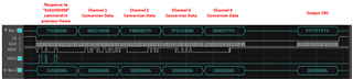
Use RREGS(4) starting with ADC1 to read contents of ADC registers.

Regards,

Todd Anderson

  • Hi Todd,

    Registers can be written to and read from while in standby mode. Most importantly, the ADC channels need to be enabled during this time. 

    What is the intention behind reading the ADC1-4 registers after sending WAKEUP? These registers only contain the gain setting information and not ADC conversion data.

    Regards,

    Ryan

  • This is from a safety viewpoint. We need to verify over time that the contents of the registers do not change because of an external noise burst. It is unlikely to happen, but the idea is to verify register contents when ADC is not being read.

    It sounds like the ADS131a04 would need to be set to standby, then read of "setup registers" then go back to normal mode using wakeup. 

    Tell me if I am off-base in my reasoning.

    By the way, can I do a WREGS of 5 registers? It appears that I can, but all of the examples in the datasheet use 4 (mainly for RREGS).

  • Hi Todd,

    Yes, more than 4 registers can be written to at once using the WREGS command.

    The ADC_ENA register should be written while in standby mode. Other registers can be written in either standby or normal mode, but it makes sense to write/read them all together during your initialization routine before returning to normal mode.

  • I noticed that WREGS writes pairs of registers.

    If I try to write 5 registers (A_SYS_CFG, D_SYS_CFG, CLK1, CLK2, ADC_ENA) I would also be writing to reserved register (next after ADC_ENA) Is that okay,

    or can I not write a zero to reserved... 

  • Hi Todd,

    It is still possible to write to an odd number of registers using the WREGS command. Figure 78 is trying to illustrate that the device only translates the first 16 bits of each command word. Therefore, even though the registers are only 8 bits wide, each word after the command word can only fit the data for two registers at a time, regardless of the device word length setting.

    As long as you specify the number of registers to write minus one, the device should stop reading the command after the data word for the ADC_ENA register and it should not try to write 0x00 to the reserved register.

    Regards,

    Ryan

  • Okay, I am confused.

    After setting up ADS and issuing WAKEUP, the ADC data is read out from the device using RREGS command, correct?

    Sequence is Command, Zero, Zero, Zero, Zero, CRC(or zero) - I have been using RREGS with ADC1 as argument, but are you saying that any command could be sent? Am I sending the wrong value in Command?

    I have been sending x3103 (RREGS - 4 registers, starting with ADC1) - what is the device expecting in Command?

  • Hi Todd,

    The conversion data is not contained in any user programmable register address. Data are directly shifted out through a dedicated output shift register, which is loaded with new data just before you see the /DRDY falling edge. You do not have to send the RREGS command to read conversion data.

    Only two registers are read at a time in each frame. Sending the command 0x3103 will output the contents of addresses 11h and 12h in the status word of the next frame (the frame after you send the command) and the contents of addresses 13h and 14h can be read in the status word of the frame after that. The remainder of the frame can still be used to read conversion data, meaning you won't miss any samples this way. Figure 76 shows an example of reading 4 registers, beginning at address 00h.

    Regards,

    Ryan

  • Above is a 20 MHz SCLK, with 6 frames, including Command followed by 5 zeroes(Bottom portion). It looks like there is valid information being presented for response at top is STATUS, ADC1 contents, ADC2, ADC3, ADC4, and 0 on MSB of CRC. Do I have correct understanding of this?

    Notice CS is active for the full 6 frames, 32-bits per frame.

  • Hi Todd - just for clarity, what you show is one data frame with six 32-bit words. I've labeled the output data words below:

    Regards,

    Ryan

  • Ryan:

    I agree with your labels. What is a good "command" to use?

  • To read conversion data, the NULL command would be simplest. The response will be the contents of the STAT_1 register.